Volkswagen Golf Service & Repair Manual: Removing and installing drive shaft
| Special tools and workshop equipment
required |
|
|
|
| Torque wrench -V.A.G 1332- |
|
|
|
| – |
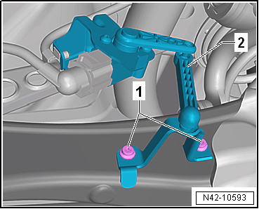
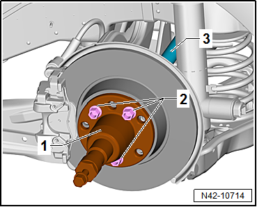
Remove retainer for rear left vehicle level sender-2-. |
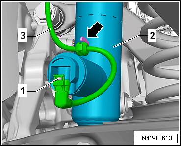
| Vehicles with adaptive chassis control DCC |
|
|
|
| – |
Disconnect connector -1- on
shock absorber -2-. |
| – |
Pull line -3- off shock
absorber -2--arrow-. |
 Note Note
| If there is moisture in the area of the connector, blow
compressed air on the contacts on the shock absorber and the
connector. |
| Vehicles with stone guard |
|
|
|
| – |
Remove spreader rivet -1-. |
| – |
Unscrew bolts -2- for stone
deflector -3-. |
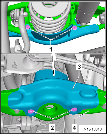
| Continuation for all vehicles |
|
|
|
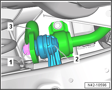
| – |
Unscrew nut -1- from coupling
rod -2-. |
| – |
Pull coupling rod -2- out of
anti-roll bar -3-. |
|
|
|
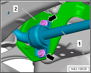
| – |
Unscrew bolts -arrows- for
anti-roll bar -1-. |
| – |
Pull anti-roll bar -1- off
subframe -2- and swing it
downwards. |
|
|
|
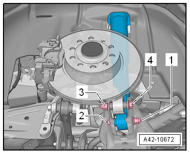
| – |
Unscrew nut -1- and pull out
bolt -2- securing shock absorber. |
| – |
Unscrew nut -3- and pull out
bolt -4- securing wheel bearing
housing. |
|
|
|
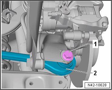
| – |
Unscrew bolt -1- for track rod
-2- and remove. |
| – |
Unbolt drive shaft at gearbox flange. |
| – |
Swing wheel bearing housing outwards and pull drive shaft
out of gearbox flange. |
| – |
Swing drive shaft downwards and remove from wheel bearing. |
| If drive shaft cannot be pulled out of the wheel bearing by
hand, use press tool -T10520-. |
|
|
|
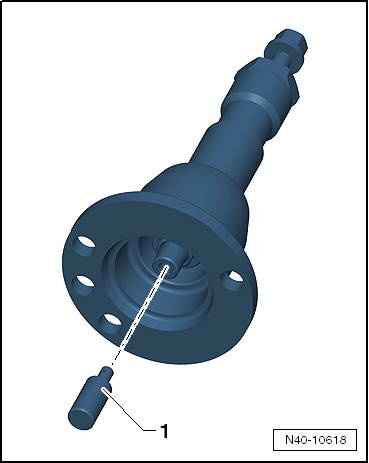
| Before using press tool -T10520- ensure that thrust piece
-1- is inserted. |
| Using press tool -T10520-: |
|
|
|
| – |
To be able to press out drive shaft
-3-, secure press tool -T10520--1-
to wheel hub using 3 wheel bolts -2-. |
|
|
|
| – |
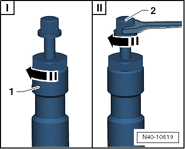
It is essential to follow specified sequence. |
| I - |
Tighten knurled nut -1-
hand-tight. |
| II - |
Turn only bolt -2- using a
spanner in order to press out drive shaft with press tool
-T10520-. |
Note
| At the end of the procedure or for pressing out drive shaft
further the spindle must be moved to its original position in
order to deploy the hydraulic force! |
| Install in reverse order of removal, observing the
following: |
| The threaded connections of the wheel bearing housing may
only be loosened and tightened in the unladen weight position
→ Chapter. |
| On vehicles with vehicle level sender, carry out basic
settings for wheel damper electronics → Vehicle
diagnostic tester. |
| Before fitting the outer joint in the wheel hub, apply a
thin coat of assembly paste to the splines on the outer joint
→ Electronic Parts Catalogue “ETKA”. |
| → Chapter „Assembly overview - drive shaft“ |
| → Chapter „Assembly overview - transverse link, multi-link
suspension, four-wheel drive“ |
| → Chapter „Assembly overview - track rod, multi-link suspension,
four-wheel drive“ |
| → Chapter „Assembly overview - suspension strut, shock absorber,
spring, multi-link suspension“ |
| → Chapter „Removing and installing rear left vehicle level
sender -G76-, multi-link suspension, front-wheel drive“ |
| → Chapter „Loosening and tightening threaded connections of
drive shaft“ |
| → Chapter „Torque settings for wheel bolts“ |
| On vehicles with vehicle level sender, carry out basic
adjustment of headlights
→ Electrical system; Rep. gr.94. |
|
|
|
1 -
Outer constant velocity joint
Renew only as complete unit
Removing
→ Fig..
Installing: drive onto shaft ...
Special tools and workshop equipment required
Thrust plate -VW 401-
Thrust plate -VW 402-
Press tool -VW 408 A-
Press t ...
Other materials:
Repairing corrugated pipe
Special tools and workshop equipment
required
Hot air blower -VAS 5179- or
Hot air blower -V.A.G 1416/- or
Hot air blower -VAS 1978/14-
...
Assembly overview – underbody covers, petrol/diesel
1 -
Front cover
Left and right
Removing and installing
→ Chapter
2 -
Underbody cover
Left and right
Removing and installing
→ Chapter
3 -
Nut
With captive
Qty. 7 on ...
Test preparations, wheel alignment with driver assist systems
The following steps are required if one or more driver
assist systems on the vehicle are to be calibrated via the
“Quick-start” procedure (i.e. without first checking and
adjusting the wheel alignment):
Before driving the vehic ...
© 2016-2026 Copyright www.vwgolf.org

 Caution
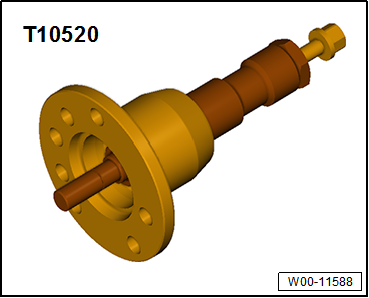
 Assembly overview - drive shaft
 Dismantling and assembling drive shaft