Volkswagen Golf Service & Repair Manual: Dismantling and assembling drive shaft
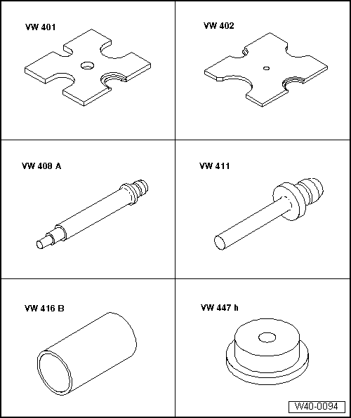
| Special tools and workshop equipment required |

| Circlip pliers -VW 161 A- |
| Torque wrench -V.A.G 1331- |
| Torque wrench -V.A.G 1332- |
| Special pliers -V.A.G 1682- |
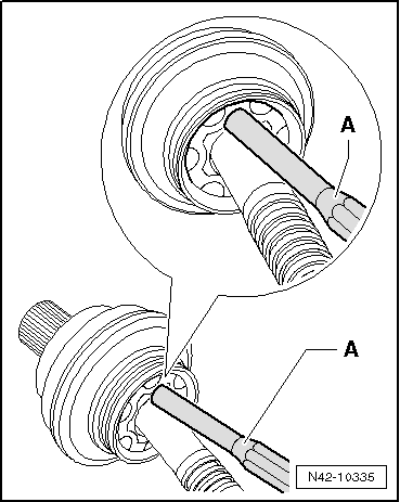
| Driving off outer constant velocity joint |
| – |
Clamp drive shaft in vice using protective jaw covers. |
| – |
Drive constant velocity joint off drive shaft using drift
-A-. |
| Drift must be positioned exactly on ball hub of constant
velocity joint. |
|
|
|
| Installation position of dished spring at outer joint |
| – |
Use plastic-headed hammer to drive joint onto shaft until
circlip engages. |
|
|
|
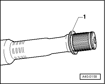
| Driving off cover for inner joint |
|
|

|
| Pressing off inner constant velocity joint |
| – |
Press off protective boot off joint using a drift. |
| – |
Remove both clamps and slide boot towards outer joint. |
|
|

|
| Installation position of dished spring at inner joint |
|
|
|
| Pressing on inner constant velocity joint |
 Note Note
| Chamfer on internal circumference of ball hub (splines) must
face contact shoulder on drive shaft. |
| – |
Press joint on to stop. |
| – |
Install retaining ring. |
|
|

|
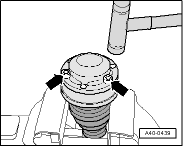
| – |
Using bolts -arrows-, align new
cover in relation to bolt holes. |
| The alignment must be very accurate, because no further
alignment is possible once the part has been hammered on. |
| – |
Drive on cover using a plastic hammer. |
|
|
|
| Tighten clamp on outer joint |
| – |
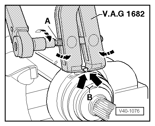
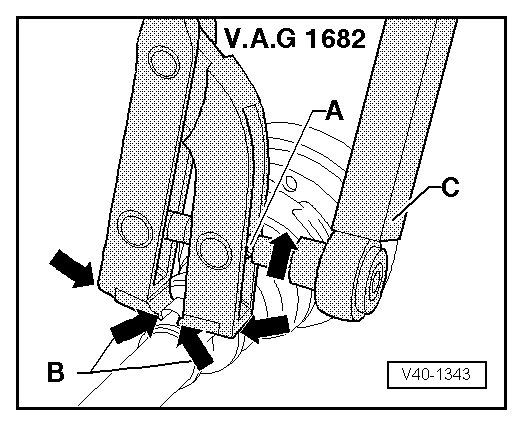
Position clamp tensioner -V.A.G 1682- as shown in diagram.
Ensure jaws of tensioner lie in corners
-arrows B- of ear on O-type clip. |
| – |
Tighten clamp by turning spindle with a torque wrench (do
not cant pliers).
|
Note
| Due to the hard material of the protective boot (compared to
rubber) and the necessity of using a stainless steel clamp, it
is only possible to tension the clamp with clamp tensioner -V.A.G
1682-. |
| Use torque wrench -C - with
setting range of 5 ... 50 Nm (e.g. torque -V.A.G 1331-). |
| Make sure thread of spindle -A-
on pliers moves freely. Lubricate with MoS2 grease if necessary. |
| If the thread is tight (e.g. due to dirt), the required
clamping force for the clamp will not be attained although the
specified tightening torque is applied. |
|
|
|
| Tightening clamp on small diameter |
|
|
|
Special tools and workshop equipment
required
Torque wrench -V.A.G 1332-
...
Special tools and workshop equipment
required
Socket, 24 mm -T10361A-
...
Other materials:
Unlocking the tailgate manually
Fig. 212 In the tailgate: opening the warning
triangle holder
Fig. 213 In the luggage compartment: unlocking
the tailgate
First read and observe the introductory information
and safety warnings
If necessary, fold the backrest of the rear bench seat forwards.
Remove items of luggage ...
Removing and installing rear bass loudspeakers -R15-/-R17-, 4-door
Rear left bass loudspeakers -R15-/rear right bass
loudspeakers -R17- are located in rear doors (bottom).
Note
Removal and installation are described for the left side.
Removal and installation on the right side are carried out i ...
Adjusting clutch engagement
The position of the engagement bearings “K 1” and “K 2” must
only be adjusted after the following work:
Clutch has been renewed.
Engaging levers were renewed.
Small ba ...
© 2016-2026 Copyright www.vwgolf.org

 Removing and installing drive shaft
 Loosening and tightening threaded connections of drive shaft