Volkswagen Golf Service & Repair Manual: Removing and installing brake servo, RHD vehicles with diesel engine
 Note Note
| If there are problems with the brake servo, first check the
brake servo vacuum system
→ Chapter. |
|
|
|
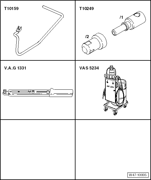
| Special tools and workshop equipment required |
| Torque wrench -V.A.G 1331- |
| Brake filling and bleeding equipment -VAS 5234- |
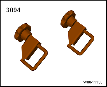
| Hose clamps, up to 25 mm -3094- |
|
|
|
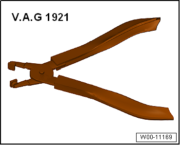
| Hose clip pliers -V.A.G 1921- |
|
|
|
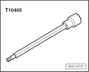
| Torx screwdriver bit T30 -T10405- |
|
|
|
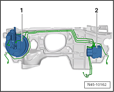
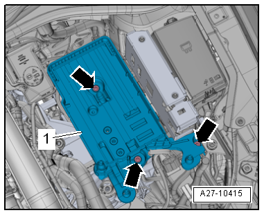
| Fitting location of brake servo in RHD vehicles: |
| 1 - |
Brake servo and brake master cylinder |
| 2 - |
ABS hydraulic unit -N55- and ABS control unit -J104- |
| – |
If vehicle has a coded radio, note radio code or, if
necessary, request it. |
| – |
Remove engine cover panel
→ Rep. gr.10. |
The fuel system is pressurised.Risk of injury due to fuel which may
spurt out.Wear eye pretection.Wear protective gloves.Release pressure:
place clean cloth around connection, and carefully open connection.
|
|
|
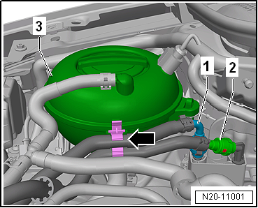
| – |
Pull off fuel supply lines -1-
and -2-. |
| – |
Separate plug-in connectors
→ Rep. gr.20. |
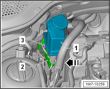
| – |
Unclip fuel lines -1- and
-2- from retainer
-arrow- on coolant reservoir
-3-. |
|
|
|
| – |
Remove securing bolts -2-. |
|
|
|
| – |
Open retainer -arrow- and
unclip fuel lines -1-. |
| – |
Then lay fuel filter to one side. |
|
|
|
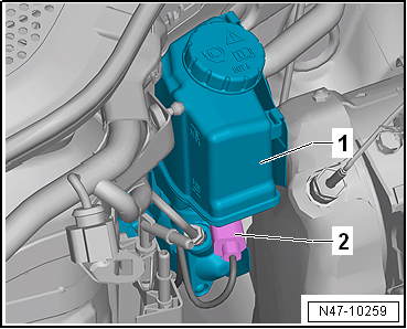
| – |
Release electrical connector -1-
and pull off. |
| – |
Release catches using a screwdriver
-arrow-. |
| – |
Place coolant expansion tank onto engine. |
|
|

|
| – |
Remove battery tray -1-
→ Electrical system; Rep. gr.27. |
| – |
Remove noise insulation
→ General body repairs, exterior; Rep. gr.66. |
| – |
Remove subframe with steering rack
→ Running gear, axles, steering; Rep. gr.40. |
| – |
Remove front exhaust pipe
→ Rep. gr.26. |
| – |
Drain coolant
→ Rep. gr.19. |
| – |
Remove left coolant pipes
→ Rep. gr.19. |
| – |
Remove rear coolant pipe
→ Rep. gr.19. |
| – |
Remove exhaust gas recirculation cooler
→ Rep. gr.26. |
|
|
|
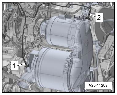
| – |
Remove exhaust gas temperature senders
-1- and -2-
→ Rep. gr.26. |
|
|
|
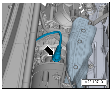
| – |
Remove Lambda probe -arrow-
→ Rep. gr.23. |
| – |
Remove emission control module
→ Rep. gr.26. |
| Vehicles with air conditioning: |
| – |
Evacuate refrigerant circuit
→ Heating, air conditioning; Rep. gr.00. |
| – |
Remove refrigerant lines with internal heat exchanger
→ Heating, air conditioning; Rep. gr.87. |
|
|
|
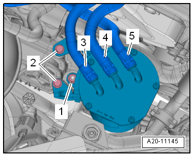
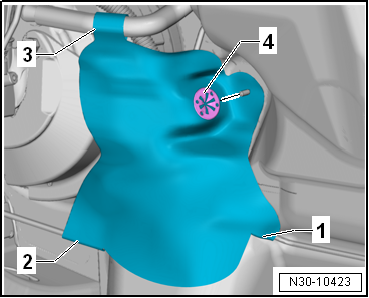
| Vehicles with manual gearbox: |
| – |
If present, remove heat shield. |
| – |
To do so, remove clamping washer -4-
from plenum chamber bulkhead. |
| – |
Open snaps -1- to
-3- on heat shield. |
|
|
|
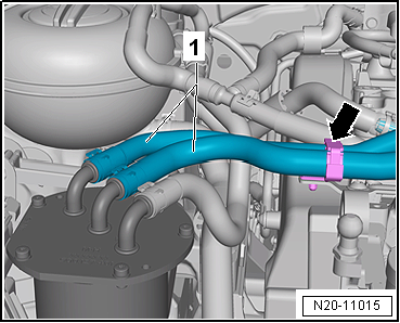
| – |
Pull return hose -2- for clutch
sender cylinder -3- off brake fluid
reservoir -4-. |
| – |
Seal return hose -2- for clutch
master cylinder -3- with sealing
tool -T10249--1- or hose clips to
25 mm -3094-. |
| – |
Raise and tie return hose -2-
in place. |
|
|
|
| Continuation for all models: |
Note
| The illustration shows installation position of ABS
hydraulic unit -N55- and ABS control unit -J104- on a LHD
vehicle. |
| – |
Place sufficient lint-free cloths in area of engine. |
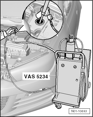
| – |
Draw off as much brake fluid as possible from brake fluid
reservoir using brake filling and bleeding equipment -VAS 5234-. |
|
|
|
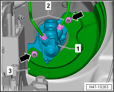
| – |
Remove heat shield -1- if
present. |
| – |
Also unscrew screw -3- with
Torx screwdriver bit T30 -T10405-. |
| – |
Pull heat shield -1- upwards
out of retainers -arrows- on brake
fluid reservoir -2-. |
|
|
|
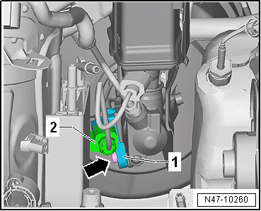
| – |
Release connector -1- and pull
off brake light switch -F--2-. |
|
|
|
| – |
Release electrical connector -2-
for brake fluid level warning contact -F34- and pull it off
brake fluid reservoir -1-. |
|
|
|
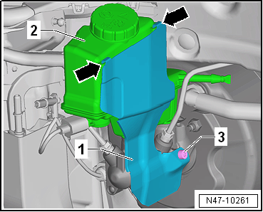
| – |
Pull out spreader rivet -3- in
-direction of arrow-. |
| – |
Pull brake fluid reservoir -1-
upwards off brake master cylinder -2- |
|
|
|
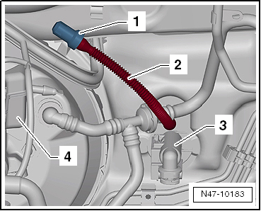
| – |
Dissipate vacuum in brake servo by depressing brake pedal
several times. |
| – |
Pull vacuum line -4- out of
brake servo -1-. |
|
|

|
| – |
Unbolt brake lines -2- from
brake master cylinder -1-. |
| – |
Detach brake lines from brake master cylinder and seal brake
lines with plugs from repair kit Part No. 1H0 698 311 A. |
| – |
Remove heat shield -3-. |
| – |
Carefully remove brake master cylinder from brake servo. |
| – |
Remove dash panel end cover on driver side
→ General body repairs, interior; Rep. gr.70. |
| – |
Remove footwell cover on driver side
→ General body repairs, interior; Rep. gr.68 |
| – |
Remove storage compartment on driver side
→ General body repairs, interior; Rep. gr.68 |
| – |
Remove dash panel cover on driver side
→ General body repairs, interior; Rep. gr.68. |
| – |
Remove knee airbag
→ General body repairs, interior; Rep. gr.69. |
|
|
|
| – |
Remove footwell vent -1- on
driver side
→ Heating, air conditioning system; Rep. gr.87. |
| – |
To do this, unscrew bolt -2-
and remove footwell vent on driver side
-1-. |
| – |
Unbolt crash bar for brake pedal and lay it to one side
→ General body repairs, interior; Rep. gr.70. |
| – |
Separate brake pedal from brake servo
→ Chapter. |
|
|

|
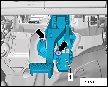
| – |
Remove nuts -arrows- from
mounting bracket. |
| – |
Remove brake servo downwards. |
| Install in reverse order of removal, observing the
following: |
Note
| The brake servo only has the additional bonded joint at the
seal when originally assembled at the factory. |
| The adhesive bond between the plenum chamber bulkhead and
the brake servo does not have to be renewed. |
| – |
Remove all adhesive residues from the plenum chamber
bulkhead and (if applicable) from the brake servo. Use adhesive
strip remover -VAS 6349- and a drill, cordless screwdriver or
grinder for this purpose. |
| – |
Operate adhesive strip remover -VAS 6349- at low speed,
working against direction of rotation. |
| – |
Carefully insert brake servo and tighten nuts. |
| – |
When assembling brake master cylinder with brake servo, make
sure push rod is properly positioned in brake master cylinder. |
| – |
When joining brake master cylinder to brake servo, make sure
seal
→ Item is properly seated. |
| – |
Ensure that seals
→ Item are correctly seated in brake master cylinder. |
| – |
Moisten sealing plugs
→ Item with brake fluid before pressing brake fluid
reservoir into brake master cylinder. |
| – |
Connect brake pedal to brake servo
→ Chapter. |
| – |
Fill coolant
→ Rep. gr.19. |
| – |
Bleed brake system
→ Chapter. |
| Vehicles with manual gearbox: |
| – |
Bleed clutch mechanism
→ Rep. gr.30. |
| Vehicles with air conditioning: |
| – |
Charge refrigerant circuit
→ Heating, air conditioning; Rep. gr.00. |
| → Chapter „Assembly overview - brake servo/brake master
cylinder, RHD vehicles“ |
| → Chapter „Removing and installing brake master cylinder, RHD
vehicles“ |
| Crash bar
→ General body repairs, interior; Rep. gr.70. |
| Footwell vents
→ Heating, air conditioning system; Rep. gr.87. |
| Knee airbag
→ General body repairs, interior; Rep. gr.69. |
| Covers on driver side
→ General body repairs, interior; Rep. gr.68 |
| Subframe
→ Running gear, axles, steering; Rep. gr.40 |
| Cooling system
→ Rep. gr.19. |
| Emission control
→ Rep. gr.26. |
| Exhaust gas recirculation
→ Rep. gr.26 |
| Exhaust system
→ Rep. gr.26 |
| Toothed belt guard
→ Rep. gr.15 |
| Exhaust gas temperature sender
→ Rep. gr.26 |
| Air conditioning
→ Heating, air conditioning; Rep. gr.87 |
| Battery
→ Electrical system; Rep. gr.27 |
| Noise insulation
→ General body repairs, exterior; Rep. gr.66. |
| Front bleed valves
→ Chapter „Assembly overview - front brake caliper“ |
| Rear bleed valves
→ Chapter „Assembly overview - rear brake caliper“ |
|
|
|
Note
If there are problems with the brake servo, first check the
brake servo vacuum system
→ Chapter.
Special tools a ...
Note
If there are problems with the brake servo, first check the
brake servo vacuum system
→ Chapter.
...
Other materials:
Dimensions
Fig. 21 Dimensions
First read and observe the introductory information
and safety warnings The data in the table apply to the most basic German
model.
The specified values can vary due to different tyre and wheel sizes, if additional
equipment is fitted, for different model versions, for ...
Aquaplus system, uni (solid-colour) and metallic colours
Designation:
Uni (solid-colour) waterborne mixing paint -LWM 075 ...-
Metallic waterborne mixing paint -LWM 076 ...-
Uni (solid-colour) waterborne base coat -LUW/LWG 038 ...-
...
Removing and installing holder for heater and air conditioning unit
Note
Leave the holders in the vehicle on removing the heater and
air conditioning unit. The illustration shows a left-hand drive
vehicle.
Removing
–
Re ...
© 2016-2026 Copyright www.vwgolf.org

 Removing and installing brake servo, LHD vehicles
 Removing and installing brake servo for vehicles with 1.2 l and 1.4 l petrol
engines
Removing and installing brake servo for vehicles with 1.2 l and 1.4 l petrol
engines