Volkswagen Golf Service & Repair Manual: Removing and installing brake servo for vehicles with 1.2 l and 1.4 l petrol
engines
 Note Note
| If there are problems with the brake servo, first check the
brake servo vacuum system
→ Chapter. |
|
|
|
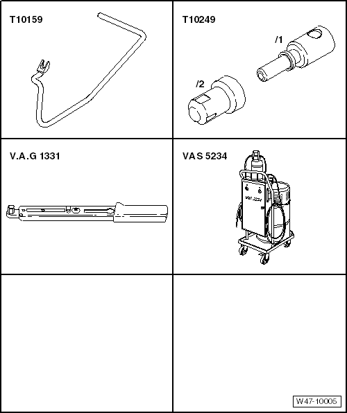
| Special tools and workshop equipment required |
| Torque wrench -V.A.G 1331- |
| Brake filling and bleeding equipment -VAS 5234- |
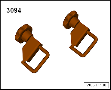
| Hose clamps, up to 25 mm -3094- |
|
|
|
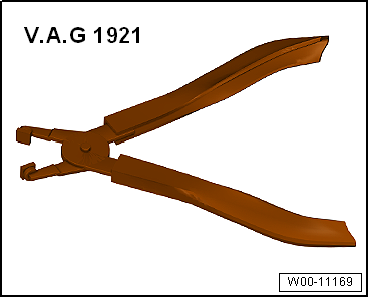
| Hose clip pliers -V.A.G 1921- |
|
|
|
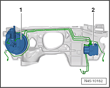
| Fitting location of brake servo in RHD vehicles: |
| 1 - |
Brake servo and brake master cylinder |
| 2 - |
ABS hydraulic unit -N55- and ABS control unit -J104- |
| – |
If vehicle has a coded radio, note radio code or, if
necessary, request it. |
| – |
Remove noise insulation
→ General body repairs, exterior; Rep. gr.66. |
| – |
Drain coolant
→ Rep. gr.19. |
|
|
|
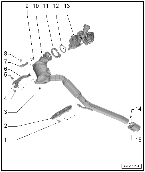
| – |
Remove catalytic converter -10-
→ Rep. gr.26. |
|
|
|
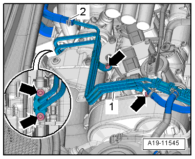
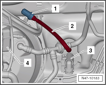
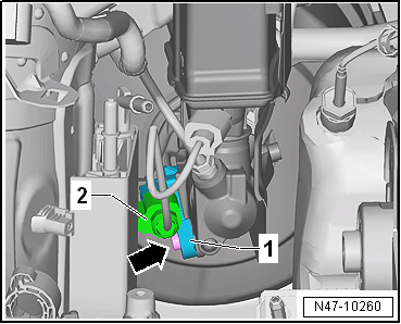
| – |
Loosen hose clip -2- and remove
coolant hose. |
| – |
Remove bolts -arrows- and
swivel coolant lines -1- to right. |
|
|
|
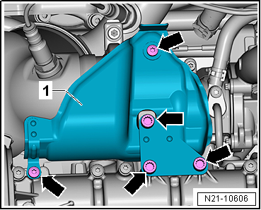
| – |
Remove heat shield -1-. |
|
|
|
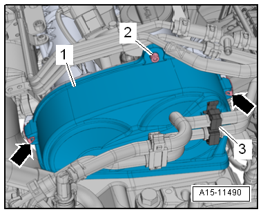
| – |
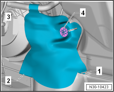
Detach hoses from retainer -3-. |
| – |
Loosen clips -arrows- and
remove upper toothed belt guard -1-. |
|
|
|
| Vehicles with manual gearbox: |
| – |
If present, remove heat shield. |
| – |
To do so, remove clamping washer -4-
from plenum chamber bulkhead. |
| – |
Open snaps -1- to
-3- on heat shield. |
|
|
|
| – |
Pull return hose -2- for clutch
sender cylinder -3- off brake fluid
reservoir -4-. |
| – |
Seal return hose -2- for clutch
master cylinder -3- with sealing
tool -T10249--1- or hose clips to
25 mm -3094-. |
| – |
Raise and tie return hose -2-
in place. |
| Vehicles with air conditioning: |
| – |
Evacuate refrigerant circuit
→ Heating, air conditioning; Rep. gr.00. |
| – |
Remove refrigerant lines with internal heat exchanger
→ Heating, air conditioning; Rep. gr.87. |
|
|
|
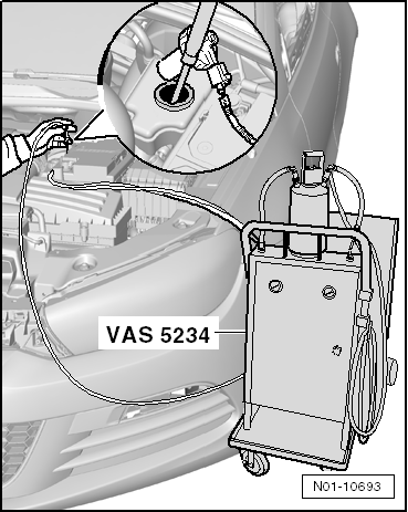
| Continuation for all models: |
| – |
Place sufficient lint-free cloths in area of engine. |
| – |
Draw off as much brake fluid as possible from brake fluid
reservoir using brake filling and bleeding equipment -VAS 5234-. |
Note
| The illustration shows installation position of ABS
hydraulic unit -N55- and ABS control unit -J104- on a LHD
vehicle. |
|
|
|
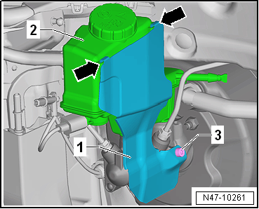
| – |
Remove heat shield -1- if
present. |
| – |
To do this, unscrew bolt -3-. |
| – |
Pull heat shield -1- upwards
out of retainers -arrows- on brake
fluid reservoir -2-. |
|
|
|
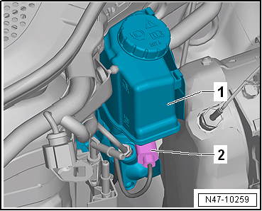
| – |
Release connector -1- and pull
off brake light switch -F--2-. |
|
|
|
| – |
Release electrical connector -2-
for brake fluid level warning contact -F34- and pull it off
brake fluid reservoir -1-. |
|
|
|
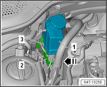
| – |
Pull out spreader rivet -3- in
-direction of arrow-. |
| – |
Pull brake fluid reservoir -1-
upwards off brake master cylinder -2- |
|
|
|
| – |
Dissipate vacuum in brake servo by depressing brake pedal
several times. |
| – |
Pull vacuum line -4- out of
brake servo -1-. |
|
|

|
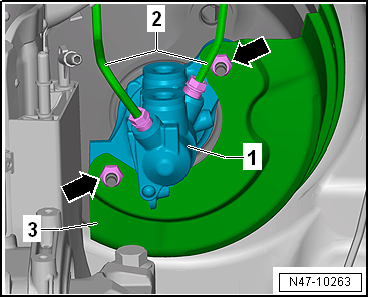
| – |
Unbolt brake lines -2- from
brake master cylinder -1-. |
| – |
Detach brake lines from brake master cylinder and seal brake
lines with plugs from repair kit Part No. 1H0 698 311 A. |
| – |
Remove heat shield -3-. |
| – |
Carefully remove brake master cylinder from brake servo. |
| – |
Remove dash panel end cover on driver side
→ General body repairs, interior; Rep. gr.70. |
| – |
Remove footwell cover on driver side
→ General body repairs, interior; Rep. gr.68 |
| – |
Remove storage compartment on driver side
→ General body repairs, interior; Rep. gr.68 |
| – |
Remove dash panel cover on driver side
→ General body repairs, interior; Rep. gr.68. |
| – |
Remove knee airbag
→ General body repairs, interior; Rep. gr.69. |
|
|
|
| – |
Remove footwell vent -1- on
driver side
→ Heating, air conditioning system; Rep. gr.87. |
| – |
To do this, unscrew bolt -2-
and remove footwell vent on driver side
-1-. |
| – |
Unbolt crash bar for brake pedal and lay it to one side
→ General body repairs, interior; Rep. gr.70. |
| – |
Separate brake pedal from brake servo
→ Chapter. |
|
|

|
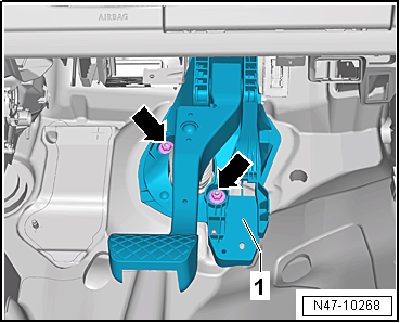
| – |
Remove nuts -arrows- from
mounting bracket. |
| Install in reverse order of removal, observing the
following: |
Note
| The brake servo only has the additional bonded joint at the
seal when originally assembled at the factory. |
| The adhesive bond between the plenum chamber bulkhead and
the brake servo does not have to be renewed. |
| – |
Remove all adhesive residues from the plenum chamber
bulkhead and (if applicable) from the brake servo. Use adhesive
strip remover -VAS 6349- and a drill, cordless screwdriver or
grinder for this purpose. |
| – |
Operate adhesive strip remover -VAS 6349- at low speed,
working against direction of rotation. |
| – |
Carefully insert brake servo and tighten nuts. |
| – |
When assembling brake master cylinder with brake servo, make
sure push rod is properly positioned in brake master cylinder. |
| – |
When joining brake master cylinder to brake servo, make sure
seal
→ Item is properly seated. |
| – |
Ensure that seals
→ Item are correctly seated in brake master cylinder. |
| – |
Moisten sealing plugs
→ Item with brake fluid before pressing brake fluid
reservoir into brake master cylinder. |
| – |
Connect brake pedal to brake servo
→ Chapter. |
| – |
Fill coolant
→ Rep. gr.19. |
| – |
Bleed brake system
→ Chapter. |
| Vehicles with manual gearbox: |
| – |
Bleed clutch mechanism
→ Rep. gr.30. |
| Vehicles with air conditioning: |
| – |
Charge refrigerant circuit
→ Heating, air conditioning; Rep. gr.00. |
| → Chapter „Assembly overview - brake servo/brake master
cylinder, RHD vehicles“ |
| → Chapter „Connecting brake lines to hydraulic unit, RHD
vehicles“ |
| Crash bar
→ General body repairs, interior; Rep. gr.70. |
| Footwell vents
→ Heating, air conditioning system; Rep. gr.87. |
| Knee airbag
→ General body repairs, interior; Rep. gr.69. |
| Covers on driver side
→ General body repairs, interior; Rep. gr.68 |
| Catalytic converter
→ Rep. gr.26 |
| Coolant lines on turbocharger
→ Rep. gr.21. |
| Toothed belt guard
→ Rep. gr.15 |
| Air conditioning
→ Heating, air conditioning; Rep. gr.87 |
| Battery
→ Electrical system; Rep. gr.27 |
| Noise insulation
→ General body repairs, exterior; Rep. gr.66. |
| Front bleed valves
→ Chapter „Assembly overview - front brake caliper“ |
| Rear bleed valves
→ Chapter „Assembly overview - rear brake caliper“ |
|
|
|
Note
If there are problems with the brake servo, first check the
brake servo vacuum system
→ Chapter.
...
Special tools and workshop equipment
required
Brake filling and bleeding equipment -VAS 5234-
...
© 2016-2024 Copyright www.vwgolf.org

 Removing and installing brake servo, RHD vehicles with diesel engine
 Removing and installing brake master cylinder, LHD vehicles