Volkswagen Golf Service & Repair Manual: Removing and installing brake servo, LHD vehicles
 Note Note
| If there are problems with the brake servo, first check the
brake servo vacuum system
→ Chapter. |
| Special tools and workshop equipment
required |
|
|
|
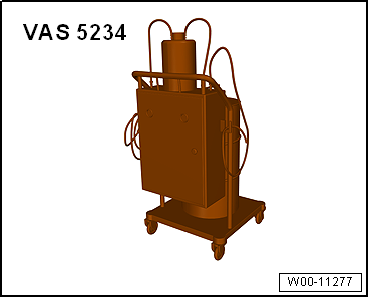
| Brake filling and bleeding equipment -VAS 5234- |
|
|
|
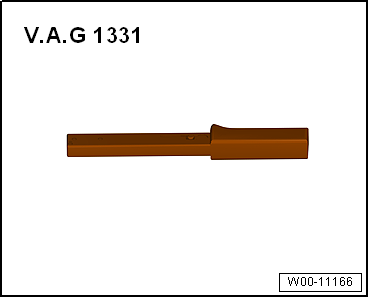
| Torque wrench -V.A.G 1331- |
|
|
|
| Adhesive strip remover -VAS 6349- |
| Drill, cordless screwdriver or grinder |
| – |
If vehicle has a coded radio, note radio code or, if
necessary, request it. |
| – |
Disconnect battery
→ Electrical system; Rep. gr.27 |
| – |
Remove battery
→ Electrical system; Rep. gr.27. |
|
|
|
| Vehicles with diesel engine: |
| – |
Remove engine cover panel. |
| – |
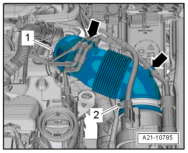
Loosen hose clip -1- and remove
air intake hose and air filter housing
→ Rep. gr.23. |
|
|
|
| – |
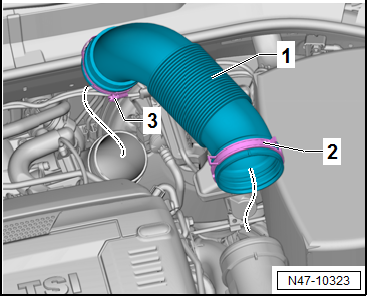
Loosen hose clips -2- and
-3-. |
| – |
Remove air intake hose -1- and
air filter housing
→ Rep. gr.24. |
| Continuation for all models: |
| – |
Remove battery tray
→ Electrical system; Rep. gr.27. |
| – |
Place sufficient lint-free cloths in area of engine and
gearbox. |
|
|
|
| – |
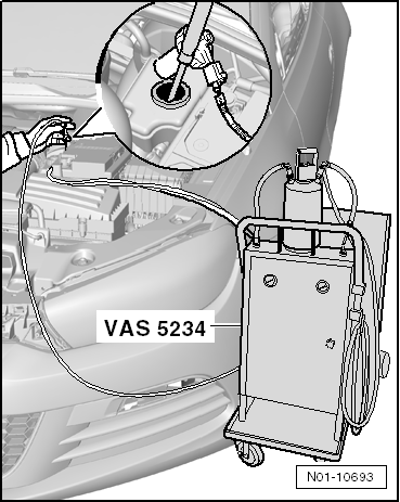
Draw off as much brake fluid as possible from brake fluid
reservoir using brake filling and bleeding equipment -VAS 5234-. |
|
|
|
| Vehicles with manual gearbox: |
| – |
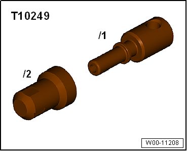
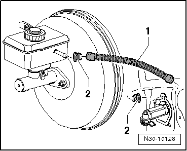
Pull off supply hose -1- for
clutch master cylinder, seal it using sealing tool -T10249- and
tie it up, or clamp off supply hose -1-
for clutch master cylinder using commercially available tool,
e.g. Hazet 4590, and pull it off. |
|
|
|
| Continuation for all models: |
| – |
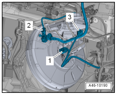
Disconnect connector from brake fluid level warning contact
-F34--3-, from vacuum sender -G608--2-
(if fitted) and from brake light switch -F--1-. |
| – |
Dissipate vacuum in brake servo by depressing brake pedal
several times. |
| – |
Pull vacuum hose out of brake servo. |
| – |
Unscrew brake lines from brake master cylinder and seal
brake lines with plugs from repair kit Part No. 1H0 698 311 A. |
| Vehicles with 7-speed dual clutch gearbox: |
| – |
Remove selector cable and cable support bracket from gearbox
→ Rep. gr.34. |
| Continuation for all models: |
| – |
Remove dash panel end cover on driver side
→ General body repairs, interior; Rep. gr.70. |
| – |
Remove footwell cover on driver side
→ General body repairs, interior; Rep. gr.68 |
| – |
Remove centre console cover on driver side
→ General body repairs, interior; Rep. gr.68. |
| – |
Remove storage compartment on driver side
→ General body repairs, interior; Rep. gr.68 |
| – |
Remove dash panel cover on driver side
→ General body repairs, interior; Rep. gr.68. |
|
|
|
| – |
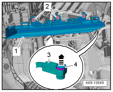
Remove knee airbag -1-
→ General body repairs, interior; Rep. gr.69. |
|
|
|
| – |
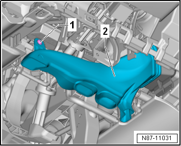
Remove footwell vent on driver side
→ Heating, air conditioning system; Rep. gr.87. |
|
|
|
| – |
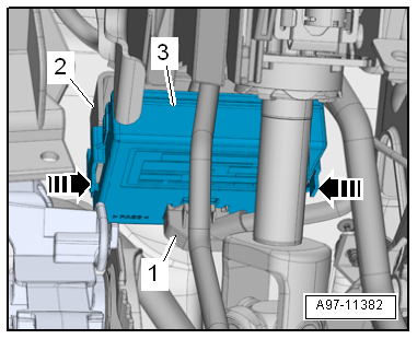
Remove control unit for data bus diagnostic interface -J533--3-
and lay it to one side
→ Electrical system; Rep. gr.97. |
|
|
|
| – |
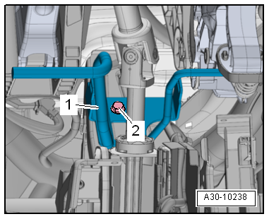
Unbolt -2- crash bar for brake
pedal -1-, detach it, and lay it to
one side
→ General body repairs, interior; Rep. gr.70. |
| – |
Separate brake pedal from brake servo
→ Chapter. |
|
|
|
| – |
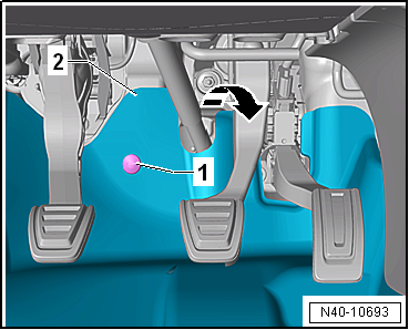
Unscrew bolts -1- and fold
footwell trim -2- in direction of
arrow towards vehicle interior. |
|
|
|
| – |
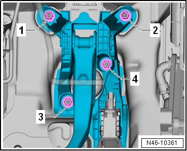
Unscrew nuts -3 and 4- from
brake servo. |
| – |
Pull brake servo off plenum chamber bulkhead, applying force
to separate bonded joint. |
| – |
Carefully remove brake servo from the vehicle. |
| – |
Unscrew nuts for brake master cylinder. |
| – |
Remove heat shield, if fitted. |
| – |
Carefully remove brake master cylinder from brake servo. |
| Install in reverse order of removal, observing the
following: |
 Note Note
| The brake servo is given the additional bonded joint only
during factory assembly. |
| The adhesive bond between the brake servo and the plenum
chamber bulkhead does not need to be renewed, but the gasket
does. |
| – |
Remove all adhesive residue from plenum chamber bulkhead
and, as needed, from brake servo. Use adhesive strip remover
-VAS 6349- with a drill, cordless screwdriver or grinder for
this purpose. |
| – |
Operate adhesive strip remover -VAS 6349- at low speed,
working against direction of rotation. |
| – |
Connect brake pedal to brake servo
→ Chapter. |
| – |
After installing, bleed brake system
→ Chapter and clutch. |
| Crash bar
→ General body repairs, interior; Rep. gr.70. |
| Footwell vents
→ Heating, air conditioning system; Rep. gr.87. |
| Knee airbag
→ General body repairs, interior; Rep. gr.69. |
| Covers on driver side
→ General body repairs, interior; Rep. gr.68 |
|
|
|
Removing
Vehicle with diesel engine:
–
Remove engine cover panel
→ ...
Note
If there are problems with the brake servo, first check the
brake servo vacuum system
→ Chapter.
...
Other materials:
Flat spots caused by storage or handling
What is a flat spot?
The terms flat area and flats are also used for the term
flat spot.
Flat spots caused by storage or handling also cause
vibration in the same way as incorrectly balanced wheels do. It
is import ...
Sprayable sealant
Designation:
Sprayable sealant -D 476 KD1 M2-, grey
Sprayable sealant -D 476 KD2 M2-, black
Issued 08.2012
Product description
Sprayable sealant -D 476 ...
Assembly overview - underbody covers, hybrid vehicles
1 -
Front cover
Left and right
2 -
Underbody cover
Left and right
Removing and installing
→ Chapter
3 -
Rear underbody cover
4 -
Bolt
For rear underbody co ...
© 2016-2026 Copyright www.vwgolf.org

 Note
Note Note
Note Removing and installing brake light switch, RHD vehicles
 Removing and installing brake servo, RHD vehicles with diesel engine


