Volkswagen Golf Service & Repair Manual: Checking pistons and cylinder bores
| – |
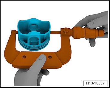
Using a micrometre, measure approx. 10 mm from the lower
edge, perpendicular to the piston pin axis. |
| Maximum deviation from nominal dimension: 0.04 mm |
|
|
|
|
Piston diameter mm |
|
Specification |
74.42
1) |
| 1) Dimensions without coating |
| Piston manufacturer Federal Mogul (thickness of 0.018 mm per
side) |
| Piston manufacturer Mahle (thickness of 0.015 mm per side) |
|
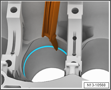
| Measuring piston ring gap |
| – |
Push piston ring at right angles to cylinder wall from above
down into cylinder bore to approx. 15 mm from bottom end of
cylinder. |
| – |
Push in using a piston without piston rings. |
|
|
|
| Piston
ring |
New
mm |
Wear
limit
mm |
| Compression
ring |
0.20
+ 0.15 |
1.0 |
| Oil scraper ring (2
parts) |
0.20
+ 0.20 |
3.0 |
| Oil scraper ring
(3 parts) |
0.50
+/- 0.25 |
3.0 |
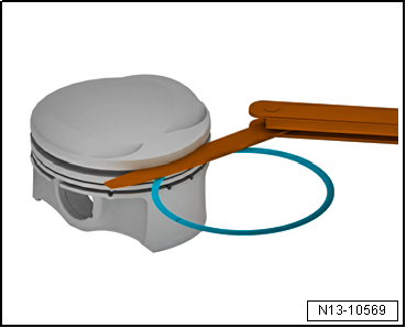
| Measuring ring-to-groove clearance |
| – |
Clean annular groove of piston before check. |
|
|
|
| Piston ring |
New
mm |
Wear limit
mm |
| 1st compression ring
(piston ring manufacturer Federal Mogul) |
0.050 … 0.090 |
0.15 |
| 1st compression ring
(piston ring manufacturer Mahle) |
0.035 … 0.085 |
0.15 |
| 2nd compression ring |
0.030 … 0.070 |
0.15 |
| Oil scraper rings (3
parts) |
Not
measurable |
| Oil scraper rings (2 parts) |
0.04 … 0.08 |
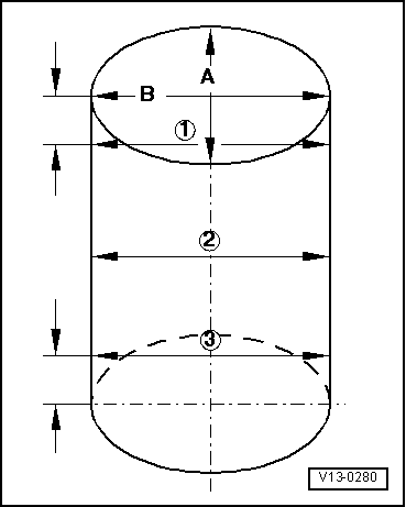
Risk of damage to the surface of the cylinder bore caused by incorrect
machining.Do not machine cylinder bore (reboring, honing, grinding) with
workshop equipment.
| – |
Using cylinder gauge -VAS 6078- take measurements at 3
positions diagonally in lateral direction
-A- and longitudinal direction -B-. |
| Maximum deviation from nominal dimension: 0.08 mm |
|
|
|
|
Cylinder bore diameter mm |
| Specification |
74.5 + 0.015
1)
+0.005 |
 Note Note
| Cylinder bores must not be measured when cylinder block is
mounted on engine and gearbox support -VAS 6095-, as
measurements may be incorrect. |
|
|
|
Special tools and workshop equipment
required
Socket -T10545-
Removing
–
Remove noi ...
Special tools and workshop equipment
required
Plastigage
Procedure
–
Remove conrod ...
© 2016-2026 Copyright www.vwgolf.org

 Removing and installing oil spray jets
 Checking radial clearance of conrods