Volkswagen Golf Service & Repair Manual: Removing and installing onboard supply control unit -J519-, RHD vehicles
 Note Note
| When renewing the control unit, select
Renew function for the respective control unit in
Guided fault finding or
Guided functions mode
→ Vehicle
diagnostic tester. |
| – |
Remove ignition key, if inserted. |
| – |
Remove glove compartment
→ General body repairs, Interior; Rep. gr.68. |
|
|
|
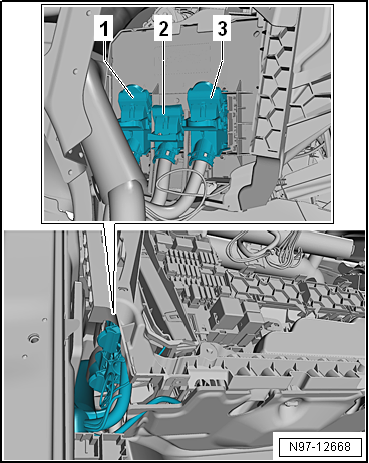
| – |
Disconnect connectors -1, 2 and 3-. |
|
|
|
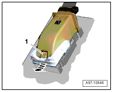
| – |
Press locking detent -1- to
disconnect connectors. |
| – |
Swing retainer in -direction of arrow-
and pull off connector. |
|
|
|
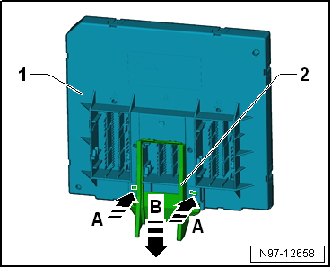
| – |
If present, remove guide -2-.
To do so, release fasteners on guide in direction of arrow
-A-. |
| – |
Remove guide -2- from onboard
supply control unit -J519--1- in
direction of arrow -B-. |
|
|
|
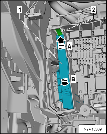
| – |
Release retaining spring at top -2-
in direction of arrow -A-. |
| – |
Pull onboard supply control unit -J519--1-
towards rear -arrow B- out of
bracket. |
| Installation is carried out in the reverse sequence. |
|
|
|
Note
When renewing the control unit, select
Renew function for the respective control unit in
Guided fault finding or
Guided functions mode
&# ...
Note
When renewing the control unit, select
Renew function for the respective control unit in
Guided fault finding or
Guided functions mode
&# ...
Other materials:
Removing and installing condensation drain (RHD)
Removing
–
Remove right centre console trim in footwell
→ General body repairs, interior; Rep. gr.68.
–
Carefully push floor covering aside and cover it in area
under condensati ...
Repairing suspension strut
Special tools and workshop equipment required
Torque wrench -V.A.G 1332-
Spring compressor -V.A.G 1752/1-
Spring retainer -V.A.G 1752/4-
Shock absorber set -T10001-
Commercially available ratchet handle ...
Balancing wheel, checking radial and lateral run-out on wheel rim
–
Attach rim to wheel balancing machine.
–
Use the centring system for wheel balancing machines -VAS
5271-.
–
Preload tyre gauge approx. 2 mm.
–
Tu ...
© 2016-2026 Copyright www.vwgolf.org

 Removing and installing onboard supply control unit -J519-, LHD vehicles
 Removing and installing data bus diagnostic interface -J533-