Volkswagen Golf Service & Repair Manual: Adjusting assembly mountings
| – |
Remove battery tray
→ Electrical system; Rep. gr.27. |
|
|
|
| – |
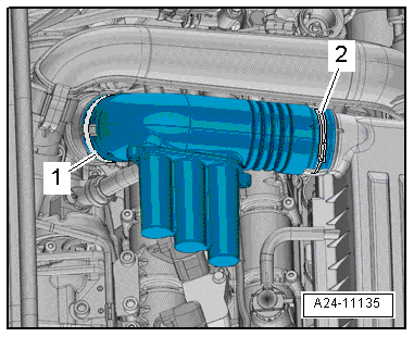
Release hose clips -1- and
-2-, and remove air pipe. |
| – |
Remove air filter housing
→ Chapter. |
| – |
Supporting engine in installation position
→ Chapter „Supporting engine in installation position“ |
|
|
|
| – |
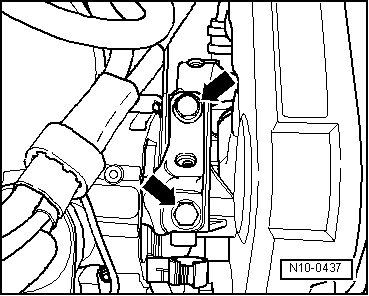
Unscrew engine mounting bolts -arrows-
one after the other and renew them (if not already renewed when
installing engine). |
| – |
First screw bolts in loosely. |
|
|
|
| – |
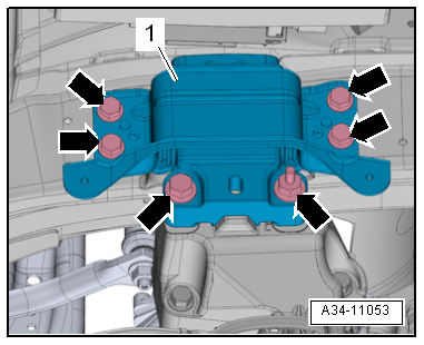
Unscrew bolts -arrows- for
gearbox mounting -1- one after the
other and renew them (if not already renewed when installing
engine). |
| – |
First screw bolts in loosely. |
|
|
|
| – |
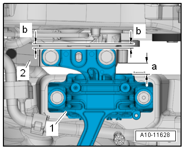
Using assembly lever, adjust engine/gearbox assembly so that
specifications listed below are attained: |
| There must be a distance of -a-
= 10 mm between engine support -2-
and engine mounting -1-. |
| Side surface of engine support casting
-2- must be located parallel to support arm of engine
mounting -1-. |
| Distance -b- = distance
-b-. |
 Note Note
| Distance -a- = 10 mm can also
be checked with a metal rod of suitable size, or similar. |
| – |
Tighten bolts for engine mounting. |
|
|
|
| – |
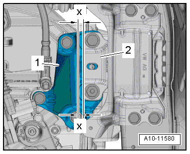
On the gearbox side, ensure that the edges of the support
arm -2- and gearbox support
-1- are parallel. |
| Distance -x- = distance
-x-. |
| – |
Tighten bolts for gearbox mounting. |
| Install in reverse order. |
| → Chapter „Assembly overview - assembly mountings“ |
| → Chapter „Assembly overview - charge air system“ |
| → Electrical system; Rep. gr.27 |
| → Chapter „Assembly overview - air filter housing“ |
| → Chapter „Assembly overview - assembly mountings“ |
|
|
|
Procedure
The following specifications must be obtained:
There must be a distance of - ...
© 2016-2026 Copyright www.vwgolf.org

 Checking adjustment of assembly mountings (engine and gearbox mountings)