Volkswagen Golf Service & Repair Manual: Removing and installing turbocharger
| Special tools and workshop equipment
required |
|
|
|
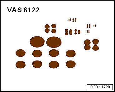
| Engine bung set -VAS 6122- |
|
|
|
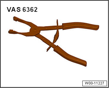
| Hose clip pliers -VAS 6362- |
 Note Note
| Observe rules for cleanliness
→ Chapter. |
| Fit all heat shield sleeves in the same place when
installing. |
| If a mechanical fault is discovered on the turbocharger
(e.g. a destroyed compressor impeller), it is not sufficient to
just renew the turbocharger. To avoid any subsequent damage, the
following work must be carried out: |
| Check air filter housing, air filter element and air inlet
hoses for contamination. |
| Check the whole charge air path and charge air cooler for
foreign objects. |
| If foreign objects are discovered in the charge air system,
clean the charge air path and, if necessary, renew the charge
air cooler. |
| – |
Drain coolant
→ Chapter. |
|
|
|
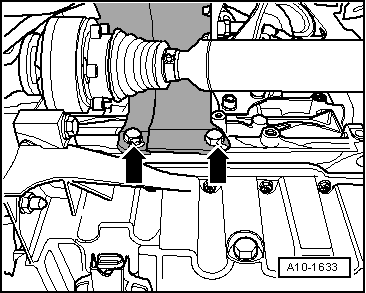
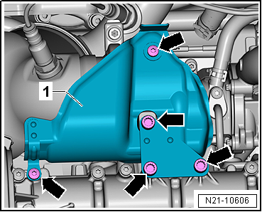
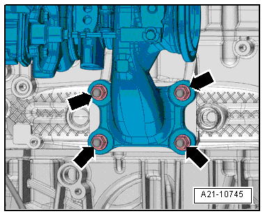
| – |
Unscrew bolts -arrows- and
remove heat shield for right drive shaft. |
|
|
|
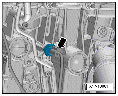
| – |
Remove heat-shield sleeve. |
| – |
Disconnect connector -arrow-
from oil pressure switch for reduced oil pressure -F378-. |
|
|
|
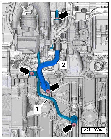
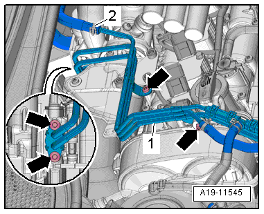
| – |
Remove bolts -arrows- and
detach oil supply line -1- and oil
return line -2-. |
|
|
|
| – |
Unscrew bolt -2- and remove
screw-type clip. |
| – |
Remove bolt -1- and nuts
-arrows- and tie up catalytic
converter. |
|
|
|
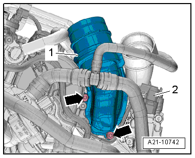
| – |
Release hose clips -1- and
-2-, and remove air pipe. |
| – |
Move air hoses clear at air pipe. |
| – |
Detach connector from charge pressure sender -GX26-. |
|
|
|
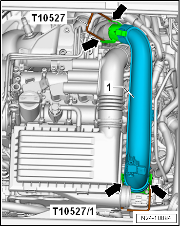
| – |
Release fasteners -arrows-
using release tools -T10527- and -T10527/1-. |
|
|
|
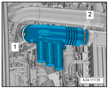
| – |
Press release tabs and disconnect hose
-1- for activated charcoal filter. |
| – |
Remove bolts -arrows- and
detach crankcase breather hose. |
|
|
|
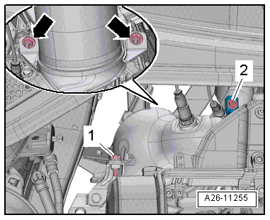
| – |
Disconnect electrical connector -2-. |
| – |
Remove bolts -arrows- and
detach connection -1-. |
|
|
|
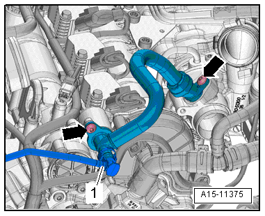
| – |
Release hose clip -2- and
detach coolant hose. |
| – |
Remove bolts -arrows- and pivot
coolant lines -1- to right side. |
|
|
|
| – |
Unscrew bolts -arrows- and
remove heat shield -1-. |
|
|
|
| – |
Unscrew nuts -arrows- and
remove turbocharger. |
| Installation is carried out in the reverse order; note the
following: |
|
|
|
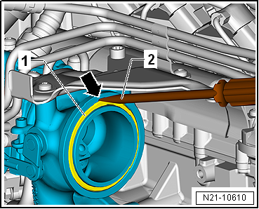
| – |
Fit screwdriver -2- in recess
-arrow- on turbocharger and lever
out seal -1-. |
Note
| Renew seals, O-rings and securing nuts of cylinder head. |
| Renew clamps for attaching catalytic converter to
turbocharger. |
| Fill turbocharger with engine oil at connection for oil
supply line. |
| Secure all hose connections with hose clips meeting
production standard
→ Electronic Parts Catalogue. |
| After installing turbocharger, run engine for about 1 minute
at idling speed to ensure that oil is supplied to turbocharger. |
| – |
Electrical connections and routing → Current
flow diagrams, Electrical fault finding and Fitting locations. |
| – |
Replenish coolant
→ Anchor. |
| → Chapter „Assembly overview - turbocharger“ |
| → Fig. „“Installing air ducts with screw-type clips”“ |
| → Fig. „“Installing catalytic converter - tightening torque and
sequence”“ |
| → Running gear, axels, steering; Rep. gr.40 |
|
|
|
1 -
Turbocharger
Removing and installing
→ Chapter
2 -
Bolt
8 Nm
3 - ...
Removing
–
Switch off ignition.
–
Disconnect electrical connecto ...
© 2016-2026 Copyright www.vwgolf.org

 Assembly overview - turbocharger
 Removing and installing charge pressure positioner -V465-