Volkswagen Golf Service & Repair Manual: Removing and installing subframe without steering rack, except for e-Golf
| Special tools and workshop equipment
required |
|
|
|
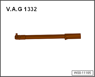
| Torque wrench -V.A.G 1332- |
|
|
|
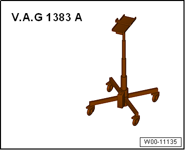
| Engine and gearbox jack -V.A.G 1383 A- |
 Note Note
| The subframe is removed together with the suspension links. |
| – |
De-energise high-voltage system
→ Rep. gr.93. |
| Continuation for all vehicles |
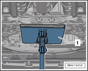
| – |
Remove lower noise insulation
→ General body repairs, exterior; Rep. gr.66. |
| For vehicles with natural gas engines |
|
|
|
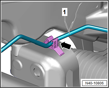
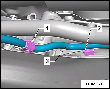
| – |
Unclip natural gas line -1-
from clip -arrow-. |
| Continuation for all vehicles |
|
|
|
| – |
Detach exhaust system bracket from subframe
-arrows-. |
|
|
|
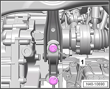
| – |
Unscrew bolts -1- for pendulum
support. |
|
|
|
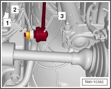
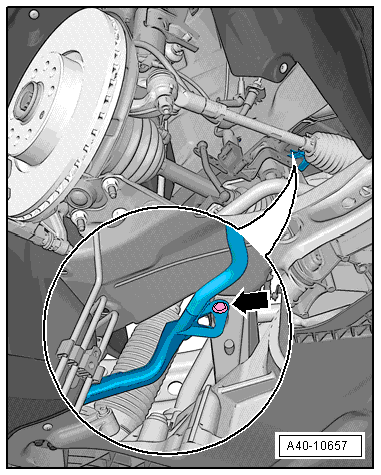
| – |
Unscrew nut -1- from coupling
rod -3- on both sides. |
| – |
Pull out coupling rod -3- from
anti-roll bar -2- on left and right
side. |
|
|
|
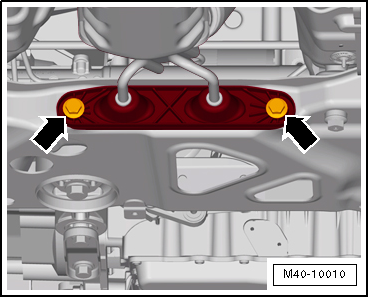
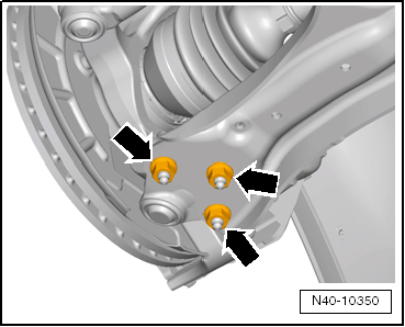
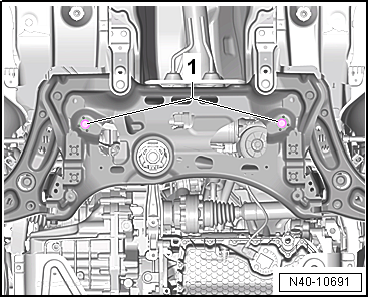
| – |
Remove nuts -arrows- on left
and right sides of vehicle. |
|
|
|
| Vehicles with vehicle level sender |
| – |
Disconnect connector -1- on
front left vehicle level sender -G78- and/or front right vehicle
level sender -G289-, as applicable. |
| Continuation for all vehicles |
|
|
|
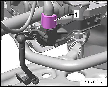
| – |
Pull wiring harness -3- clips
-1- and -2-
off subframe and steering rack. |
| Unclip high-voltage cable from subframe. |
| Continuation for all vehicles |
|
|
|
| – |
Remove bolts -1- for steering
rack. |
| – |
Prise steering rack out of dowel sleeves of subframe. |
|
|
|
| – |
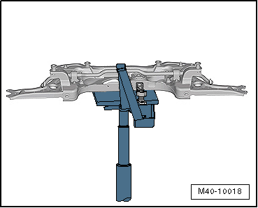
Position engine and gearbox jack -V.A.G 1383 A--1-
under subframe |
| – |
Fixing subframe
→ Chapter and lowering approx. 10 cm. |
|
|
|
| – |
Pull out spreader clip -arrow-. |
| – |
Lower subframe with engine and gearbox jack -V.A.G 1383 A-. |
|
|
|
| – |
Secure subframe on engine and gearbox jack -V.A.G 1383 A-. |
| – |
Secure steering rack to body. |
| Install in reverse order of removal, observing the
following: |
| – |
On vehicles with vehicle level sender, carry out basic
settings for wheel damper electronics → Vehicle
diagnostic tester. |
| → Chapter „Assembly overview - subframe“ |
| → Chapter „Assembly overview - steering rack“ |
| Bolts for pendulum support
→ Rep. gr.10. |
| Bolts for noise insulation
→ General body repairs, exterior; Rep. gr.66. |
| Exhaust system to subframe
→ Rep. gr.26. |
| → Chapter „Torque settings for wheel bolts“ |
| If a crooked steering wheel is determined during the road
test even though locating pins -T10486/1- were used, check wheel
alignment. In this case the wheel alignment test results must be
archived in the vehicle files. |
|
|
|
1 -
Anti-roll bar with rubber bush
Removing and installing
→ Chapter
2 -
Nut
When tightening, cou ...
Special tools and workshop equipment
required
Ball joint puller -T10187-
...
Other materials:
Safety precautions during road tests in which test and measuring equipment
is used
Safety precautions during road tests in which test
and measuring equipment is used
Risk of injury due to unsecured test and measuring equipment
If a front passenger airbag is triggered during an accident,
unsecured test and measuring equipment can become dang ...
Mechanical controls on the front seat
Fig. 43 Front left-hand seat controls
First read and observe the introductory information
and safety warnings The layout of the controls on the front right-hand seat
is a mirror image of the layout of the controls on the front left-hand seat.
The following section contains a description o ...
Removing and installing vibration damper
Special tools and workshop equipment
required
Counterhold -T10475-
Removing
–
Remove noise insulation
→ General body repairs, ...
© 2016-2026 Copyright www.vwgolf.org

 Assembly overview - subframe
 Removing and installing subframe with steering rack, LHD vehicles, except
for e-Golf
Removing and installing subframe with steering rack, LHD vehicles, except
for e-Golf