Volkswagen Golf Service & Repair Manual: Removing and installing subframe with steering rack, LHD vehicles, except
for e-Golf
| Special tools and workshop equipment
required |
|
|
|
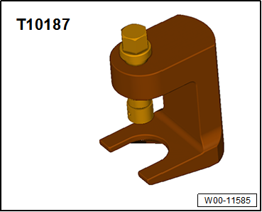
| Ball joint puller -T10187- |
|
|
|
| Torque wrench -V.A.G 1332- |
| – |
Turn steering wheel to straight-ahead position and remove
ignition key so that the steering lock engages. |
| Vehicles with keyless entry and start system “Keyless
Access” |
| – |
Switch off ignition and open driver's door so that the
steering lock engages. |
| – |
De-energise high-voltage system
→ Rep. gr.93. |
| Continuation for all vehicles |
| – |
Disconnect battery
→ Electrical system; Rep. gr.27. |
| Continuation for all vehicles |
|
|
|
| – |
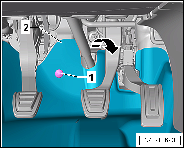
Unscrew bolts -1-, and fold
footwell trim -2- in
-direction of arrow- towards
vehicle interior. |
|
|
|
| – |
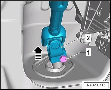
Unscrew bolt -1- from universal
joint -2- and pull off universal
joint in -direction of arrow-. |
 Caution
| The following work must not be performed while the
universal joint is separated from the steering rack: |
| Not adhering to these instructions will result in
irreparable damage. |
|
| – |
Remove lower noise insulation
→ General body repairs, exterior; Rep. gr.66. |
| For vehicles with natural gas engines |
|
|
|
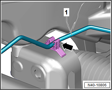
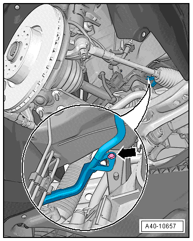
| – |
Unclip natural gas line -1-
from clip -arrow-. |
| Continuation for all vehicles |
|
|
|
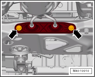
| – |
Detach exhaust system bracket from subframe
-arrows-. |
|
|
|
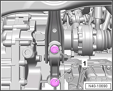
| – |
Unscrew bolts -1- for pendulum
support. |
|
|
|
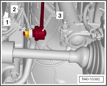
| – |
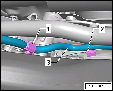
Unscrew nut -1- from coupling
rod -3- on both sides. |
| – |
Pull out coupling rod -3- from
anti-roll bar -2- on left and right
side. |
|
|
|
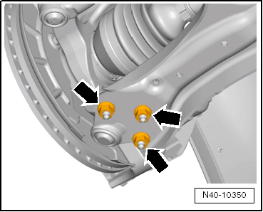
| – |
Remove nuts -arrows- on left
and right sides of vehicle. |
| – |
Pull swivel joint out of suspension link. |
| – |
Loosen nut on track rod ball joint but do not remove
completely. |
|
|
|
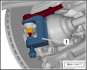
| – |
Using ball joint puller -T10187--1-,
press track rod ball joint off wheel bearing housing, and
unscrew nut. |
C aution
| Leave nut screwed on a few turns to protect thread
on pin. |
|
| Vehicles with vehicle level sender |
|
|
|
| – |
Disconnect connector -1- on
front left vehicle level sender -G78- and/or front right vehicle
level sender -G289-, as applicable. |
| Continuation for all vehicles |
|
|
|
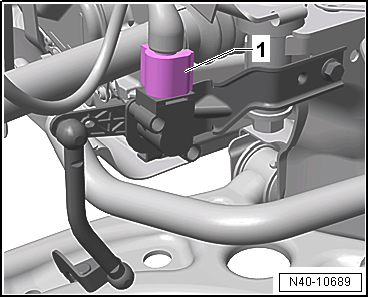
| – |
Disconnect connector -1- for
oil level and oil temperature sender -G266-. |
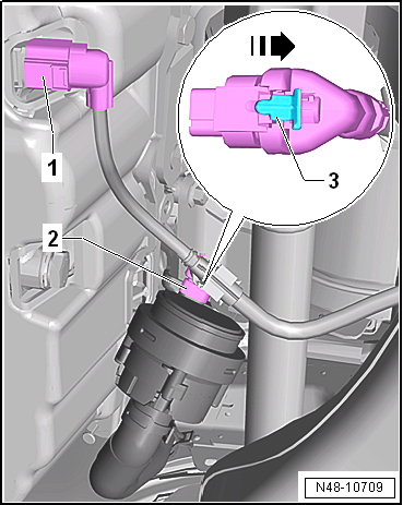
| – |
If fitted, disconnect connector -2-
on continued coolant circulation pump -V51-. Open locking
mechanism -3- in
-direction of arrow-, and release
connector. |
|
|
|
| – |
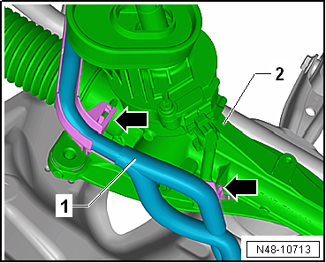
Pull wiring harness -3- clips
-1- and -2-
off subframe and steering rack. |
| Unclip high-voltage cable from subframe. |
| Continuation for all vehicles |
|
|
|
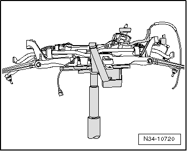
| – |
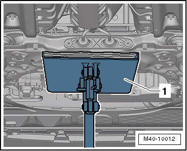
Position engine and gearbox jack -V.A.G 1383 A--1-
under subframe |
| – |
Fixing subframe
→ Chapter and lowering approx. 10 cm. |
|
|
|
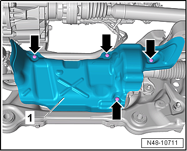
| – |
Unscrew bolts -arrows-, and
remove heat shield -1- from
steering rack. |
 Note Note
| Different heat shields -1- are
installed depending on the engine. On some engines it is
possible to access the connectors for the steering rack without
removing the heat shield. |
|
|
|
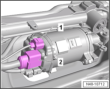
| – |
Disconnect connectors -1- and
-2- from steering rack. |
|
|
|
| – |
Unclip wiring harness -1- from
steering rack -2--arrows-. |
|
|
|
| – |
Pull out spreader clip -arrow-. |
| – |
Lower subframe with engine and gearbox jack -V.A.G 1383 A-. |
|
|
|
| – |
Secure subframe to engine and gearbox jack -V.A.G 1383 A-
with the appropriate strap. |
| Install in reverse order of removal, observing the
following: |
Note
| Coat seal on steering rack with suitable lubricant, e.g.
soft soap, before installing steering rack. |
| After fitting the steering rack to the universal joint
ensure that the seal is not kinked against the assembly plate on
the steering rack. The opening to the footwell must be sealed
correctly. Otherwise, this can result in water leaks and/or
noise. |
| Ensure sealing surfaces are clean. |
| – |
On vehicles with vehicle level sender, carry out basic
settings for wheel damper electronics → Vehicle
diagnostic tester. |
| → Chapter „Assembly overview - subframe“ |
| → Chapter „Assembly overview - wheel bearing assembly“ |
| → Chapter „Assembly overview - steering rack“ |
| → Chapter „Assembly overview - steering column“ |
| Bolts for pendulum support
→ Rep. gr.10. |
| Bolts for noise insulation
→ General body repairs, exterior; Rep. gr.66. |
| Exhaust pipes double clamp
→ Rep. gr.26. |
| → Chapter „Torque settings for wheel bolts“ |
| If a crooked steering wheel is determined during the road
test even though locating pins -T10486/1- were used, check wheel
alignment. In this case the wheel alignment test results must be
archived in the vehicle files. |
|
|
|
Special tools and workshop equipment
required
Torque wrench -V.A.G 1332-
...
Special tools and workshop equipment
required
Ball joint puller -T10187-
...
Other materials:
Ignition lock
Fig. 128 Positions of the vehicle key in
the ignition lock
First read and observe the introductory information
and safety warnings The steering lock can be activated when there is no vehicle
key in the ignition lock.
Vehicle key positions
Ignition switched off. The vehicle key ca ...
General information
Repair instructions for repair work on ABS
The ABS brake system is divided diagonally. The
servo-assistance is effected pneumatically by the vacuum brake
servo unit.
Vehicles with ABS are not fitted with a mechanical brake
pressure regu ...
Removing and installing vacuum sender -G608
Note
The vacuum sender -G608- is only installed in selected
petrol engines.
Removing
On »R« vehicles:
–
Open clamp -2- and screw-typ ...
© 2016-2026 Copyright www.vwgolf.org

 Removing and installing subframe without steering rack, except for e-Golf
 Removing and installing subframe with steering rack, RHD vehicles, except
for e-Golf
Removing and installing subframe with steering rack, RHD vehicles, except
for e-Golf