Volkswagen Golf Service & Repair Manual: Removing and installing heat exchanger for high-voltage battery
| Special tools and workshop equipment
required |
| Hose clamps, up to 25 mm -3094- |
| Engine bung set -VAS 6122- |
| Pliers for spring-type clips -VAS 5024A- |
| Cooling system tester -V.A.G 1274 B- |
| – |
Observe safety precautions
→ Chapter „Safety precautions when handling refrigerants“. |
| – |
Comply with notes
→ Chapter „Working on refrigerant circuit“. |
| – |
Observe safety precautions
→ Chapter „Safety precautions when working on the cooling
system“. |
| – |
Observe safety precautions when working in the vicinity of
high-voltage components
→ Chapter „Safety precautions when working in the vicinity of
high-voltage components“. |
| – |
Observe the risk category of the high-voltage system
→ Rep. gr.00. |
| – |
Extract refrigerant using air conditioner service station
before opening refrigerant circuit. |
 Note Note
| To prevent the intrusion of moisture, all components of the
refrigerant circuit which have been opened must be sealed with
suitable plugs. |
When the engine is warm, the cooling system is under pressure. Danger of
scalding due to steam and hot coolant. There is a risk of injury to the
skin and parts of the body due to scalding.Always wear safety
gloves.Always wear safety goggles.Proceed as follows to release the
pressure: cover the cap of the coolant expansion tank with a cloth, and
open it carefully.
| – |
Open filler cap on coolant expansion tank for high-voltage
system
→ Rep. gr.19. |
| – |
Detach coolant expansion tank for coolant circuit of engine
from vehicle, and slightly tilt it to the side
→ Rep. gr.19. |
|
|
|
| – |
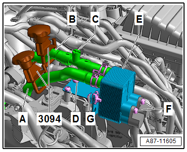
Clamp off coolant hoses -A- and
-B- using hose clamps -3094-. |
Note
| The heat exchanger is designed for a particular direction of
flow of the coolant. Therefore, the coolant hoses must not be
interchanged when connecting them. |
| – |
Cover area beneath connections for coolant hoses on heat
exchanger -E- with absorbent paper. |
| – |
Disconnect coolant hoses -A-
and -B- from connections on heat
exchanger -E-. |
| – |
Seal open connections for coolant hoses on heat exchanger
-E- with clean plugs from engine
bung set -VAS 6122-. |
| – |
Remove bolts -F- on refrigerant
lines to heat exchanger -E-. |
|
|
|
| – |
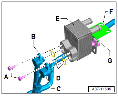
Detach heat exchanger -C- from
refrigerant lines -B- and
-C-, and remove it together with
bracket -F-. |
| – |
Seal open connections for coolant hoses on heat exchanger
-E- and refrigerant lines
-B- and -C-
with clean plugs from engine bung set -VAS 6122-. |
Note
| Bracket -F- is secured to the
heat exchanger -E- with two bolts
-G-. |
| Installation is carried out in the reverse order. When
installing, note the following: |
| – |
Renew seals -D-; for correct
version refer to
→ Electronic Parts Catalogue. |
| – |
Check connections of refrigerant lines (-B-
and -C-) and on heat exchanger
-E- for soiling and damage. |
|
|
|
| – |
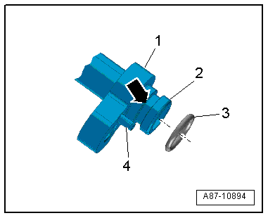
Insert seal -3- into groove
-arrow- on connection of
refrigerant line -1-. |
Note
| If fitted, check that dowel pin -4-
is not damaged and is seated correctly. |
| Moisten seals with refrigerant oil before installing
→ Chapter. |
| Make sure seals are seated correctly in groove of
corresponding refrigerant line. |
|
|
|
| – |
Bracket -F- is secured to the
heat exchanger -E- with two bolts
-G-. If the bolts
-G- have been loosened, insert
them, but do not tighten them yet. |
| – |
Install refrigerant lines -B-
and -C- to heat exchanger
-E-, and secure them with bolts
-A- (do not tighten bolts
-A- yet). |
|
|
|
| – |
Align heat exchanger -E- free
of stress, and insert bolts -D-. |
| – |
Tighten bolts -G- (specified
torque 8 Nm). |
| – |
Tighten bolts -D- (specified
torque 8 Nm). |
| – |
Tighten bolts -F- (specified
torque 8 Nm). |
| – |
Connect coolant hoses -A- and
-B- to connections on heat
exchanger -E-. |
| – |
Fill coolant in coolant expansion tank for high-voltage
system
→ Rep. gr.19. |
| – |
Slightly increase pressure in coolant expansion tank for
high-voltage system using e.g. cooling system tester -V.A.G 1274
B-
→ Rep. gr.19. |
| – |
Carefully open bleeder valve -C-. |
| – |
Carefully open hose clamp -3094- on coolant hose
-A-, and let coolant flow into heat
exchanger -E-. |
| – |
As soon as coolant escapes from bleeder valve
-C-, close bleeder valve
-C-. |
Note
| If the heat exchanger for high-voltage battery
-E- has been removed and installed
as described above, there should not be any air in the coolant
circuit of the high-voltage system. If, however, there is still
air in the coolant circuit, bleed coolant circuit
→ Rep. gr.19. |
| – |
If necessary, fill coolant in coolant expansion tank for
high-voltage system
→ Rep. gr.19. |
| – |
Remove hose clamp -3094-, and reinstall all components which
have been removed or detached. |
| – |
The remaining steps for installation are carried out in
reverse order. |
| – |
As a final step, read event memory, and clear any entries
displayed using cooling system tester in “Guided fault finding”
mode. |
|
|
|
Removing
–
Observe safety precautions
→ Chapter „Safety precautions when handling refrigerants“.
...
Observe safety precautions
→ Chapter „Safety precautions when handling refrigerants“.
–
Comply with notes
→& ...
© 2016-2024 Copyright www.vwgolf.org

 Removing and installing refrigerant shut-off valve for high-voltage battery
heat exchanger -N542
Removing and installing refrigerant shut-off valve for high-voltage battery
heat exchanger -N542 Refrigerant line with restrictor