Volkswagen Golf Service & Repair Manual: Removing and installing flap for charging bay
| – |
Removing radiator grille
→ Chapter |

| – |
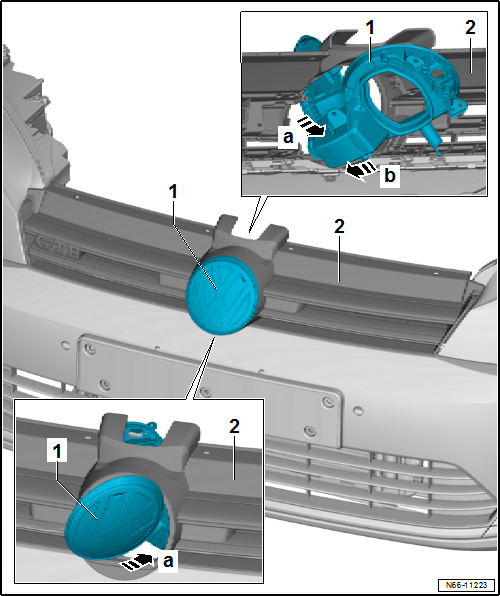
Push flap for charging bay -1- towards
side, -arrow a-. |
| – |
Swing flap for charging bay -1- through
radiator grille -2- towards outside
-arrow b-. |
| – |
Swing flap for charging bay -1- through
radiator grille -2- towards inside
-arrow a-. |
| – |
Push flap for charging bay -1- towards
side to its installation position, -arrow b-. |
| |
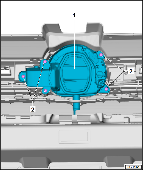
Bolts on flap for charging bay
→ Item |
Removing
Note
On vehicles with a flap for the charging bay in the radiator grille,
the connector must be disconnect ...
Removing
–
Removing radiator grille
→ Chapter
–
Remove bolts -2-.
...
Other materials:
Introduction
This chapter contains information on the following subjects:
→ Displays
→ Description
ProActive occupant protection is an assistance system that initiates action to
protect vehicle occupants in dangerous situations. However, the system cannot prevent
a collision.
Add ...
Removing and installing model designation on radiator grille
Note
The description applies for all emblems. Here the “GTI”
emblem is shown as an example.
Removing
–
Removing radiator grille
→ Chapter
– ...
Checking operation and power supply of fuel pump
Special tools and workshop equipment
required
Removal wedge -3409-
Multimeter e.g. hand-held multimeter -V.A.G 1526E-
...
© 2016-2026 Copyright www.vwgolf.org

 Removing and installing radiator grille
 Removing and installing actuator