Volkswagen Golf Service & Repair Manual: Checking operation and power supply of fuel pump
| Special tools and workshop equipment
required |
|
|
|
| Multimeter e.g. hand-held multimeter -V.A.G 1526E- |
|
|
|
| Auxiliary measuring set -V.A.G 1594C- |
| Vehicle diagnostic tester |
| Battery voltage must be at least 11.5 V. If necessary,
charge battery
→ Electrical system; Rep. gr.27. |
| Fuse for fuel pump control unit -J538- OK
→ Current
flow diagrams, Electrical fault finding and Fitting locations. |
| Fuel pump control unit -J538- OK → Vehicle
diagnostic tester. |
 Note Note
| Function of fuel pump is checked using final control
diagnosis. |
| – |
Observe safety precautions
→ Chapter. |
| – |
Observe rules for cleanliness
→ Chapter. |
|
|
|
| – |
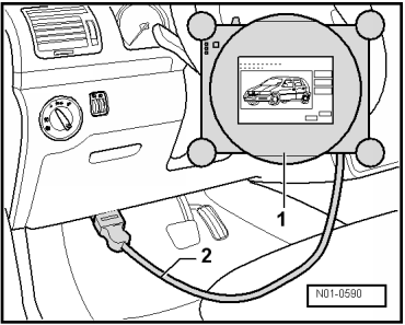
Connect vehicle diagnostic tester-1-
as follows: |
| – |
Connect diagnosis cable connector -2-
to diagnostic connection in driver footwell. |
| – |
Select final control diagnosis for fuel pump in vehicle
self-diagnosis program. |
| The fuel pump must now run slowly up to maximum speed. |
Note
| The fuel pump runs very quietly. |
| If the final control diagnosis is to be carried out several
times in succession, it may be necessary to start the engine
briefly before repeating the final control diagnosis. |
| If fuel pump does not run: |
|
|
|
| – |
Remove right rear seat
→ General body repairs, interior; Rep. gr.72. |
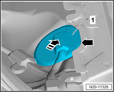
| – |
Partially detach cover -1- in
floor covering at parting line -arrow-. |
| – |
Do not detach cover completely from floor covering in order
to ensure it is reinstalled in the correct installation
position. |
| – |
Detach it just enough that the cover can be folded upwards. |
| – |
Fold up cover in -direction of arrow-. |
| – |
Remove rear bench seat
→ General body repairs, interior; Rep. gr.72. |
|
|
|
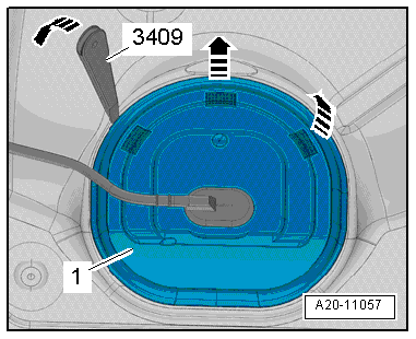
| Continuation for all vehicles: |
| – |
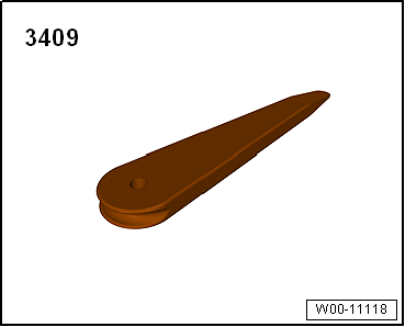
Unclip cover -1- for flange on
right at retaining tabs -arrows-,
using removal wedge -3409-. |
|
|
|
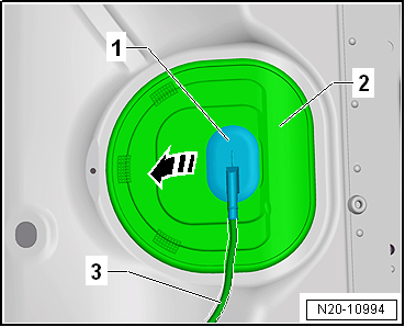
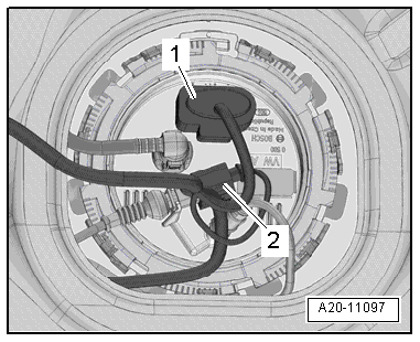
| – |
Unclip sealing grommet -1-
downwards from cover -2-. |
| – |
Push cover -2- back along
wiring harness -3-. |
|
|
|
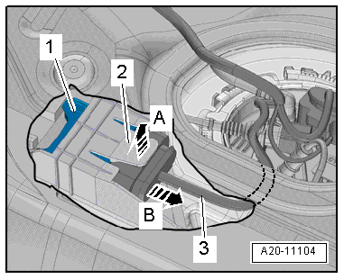
| – |
Press up tab -2- in
-direction of arrow A-; to do so,
reach between floor panel and fuel tank with your finger. |
| – |
At the same time, carefully pull fuel pump control unit
-J538--1- out of mounting
-in direction of arrow B- by
grasping hold of wiring harness -3-. |
| – |
Guide fuel pump control unit -J538- out towards interior
between fuel tank and floor panel. |
| – |
Ensure that connector on fuel pump control unit -J538- is
fitted securely by pulling connector without pressing catch. If
connector was not inserted correctly, repeat functional check of
fuel pump. |
| – |
Release and pull off connector from fuel pump control unit
-J538-. |
| – |
Check contacts on connector and on fuel pump control unit
-J538- for damage. |
|
|
|
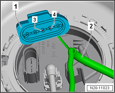
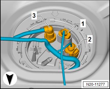
| – |
Check voltage supply between contacts
-3- and -4- using multimeter
→ Current flow diagrams, Electrical fault finding and Fitting
locations. |
| – |
Use auxiliary measuring set -V.A.G 1594C- to do this. |
| Specification: approx. battery voltage |
| If the specification is not attained: |
| – |
Locate and eliminate open circuit referring to current flow
diagram → Current
flow diagrams, Electrical fault finding and Fitting locations. |
|
|
|
| If specification is attained on vehicles with front-wheel
drive: |
| – |
Check that connector -1- is
fitted securely by pulling connector without pressing catch. If
connector was not inserted correctly, repeat functional check of
fuel pump. |
| – |
Release and pull off connector -1-. |
| – |
Check contacts on plug and on fuel delivery unit for damage. |
| – |
Check wiring harness between fuel pump control unit -J538-
and fuel delivery unit → Current
flow diagrams, Electrical fault finding and Fitting locations. |
|
|
|
| If specification is attained on vehicles with four-wheel
drive: |
| – |
Check that connector -1- is
fitted securely by pulling connector without pressing catch. If
connector was not inserted correctly, repeat functional check of
fuel pump. |
| – |
Release and pull off connector -1-. |
| – |
Check contacts on plug and on fuel delivery unit for damage. |
| – |
Check wiring harness between fuel pump control unit -J538-
and fuel delivery unit → Current
flow diagrams, Electrical fault finding and Fitting locations. |
|
|
|
The fuel system is pressurised.Risk of injury due to fuel which may
spurt out.Wear eye protection.Wear protective gloves.Release pressure:
place clean cloth around connection and carefully open connection.
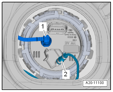
| – |
Draining fuel tank
→ Chapter |
| – |
Pull fuel line -1- off flange.
Separate plug-in connectors
→ Chapter. |
| Vehicles with auxiliary heater: |
| – |
Remove fuel line -2- leading to
metering pump -V54- for auxiliary heater from sealing flange. |
| – |
To do this, open clip at bottom. |
| – |
Carefully pull out fuel line -2-. |
|
|
|
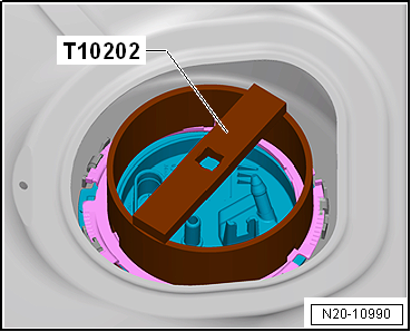
| Continuation for all vehicles: |
| – |
Open locking ring using wrench -T10202-. |
| – |
Check that electrical wires between flange and fuel pump are
connected. |
|
|
|
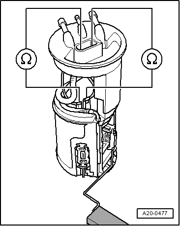
| – |
Check electrical wiring between flange and fuel pump for
continuity using an ohmmeter. |
| – |
Check contacts for damage. |
| If no open circuit can be found: |
| – |
Fuel pump is defective, renew fuel delivery unit
→ Chapter. |
|
|
|
Special tools and workshop equipment
required
Removal wedge -3409-
...
Other materials:
Removing and installing accelerator module -GX2-
Removing
–
Fold floor covering -1-
forwards in -direction of arrow-.
–
Release and pull off connector -2-
...
Removing and installing insulation
Removing
–
Lever retaining clips -2- out of bonnet
-3- using removal lever -80-200-.
–
Pull insulation -1- out of elongated
holes -arrows-.
Inst ...
SAFELOCK mechanism
First read and observe the introductory information
and safety warnings Depending on the vehicle equipment level, the vehicle
may have a SAFELOCK mechanism and anti-theft alarm .
Function
Action
Locking the vehicle and activating the SAFELOCK me ...
© 2016-2026 Copyright www.vwgolf.org

 Fuel pump
 Checking function and voltage supply of the fuel pump, engine code CWVA