Volkswagen Golf Service & Repair Manual: Removing and installing Denso heat exchanger, LHD vehicles
| Special tools and workshop equipment
required |
|
|
|
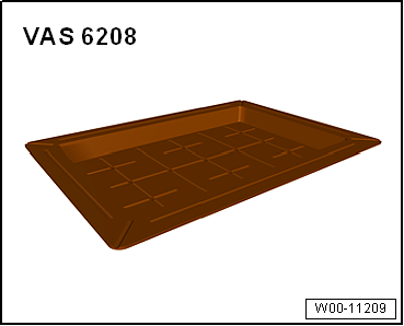
| Drip tray for workshop hoist -VAS 6208- |
|
|
|
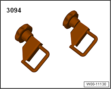
| Hose clamps up to 25 mm -3094- |
| Compressed air gun, commercially available |
|
|
|
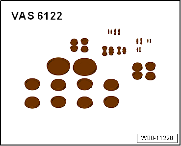
| Engine bung set -VAS 6122- |
| – |
Heed the safety precautions
→ Chapter „Safety instructions“. |
|
|
|
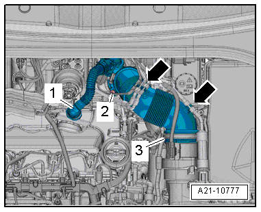
| Vehicles with TDI engine: |
| – |
Press release buttons on crankcase breather hose
-1- and detach hose from cylinder
head cover. |
| – |
Detach vacuum hoses from air pipe
-arrows- to permit access. |
| – |
Remove bolt -2-, swivel air
pipe with connection rearwards and detach from turbocharger. |
|
|
|
| Continuation for all vehicles: |
| – |
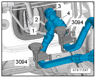
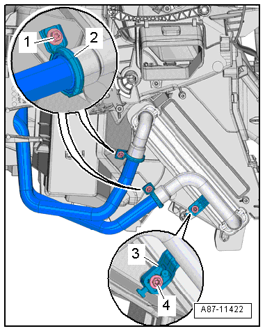
Mark installation position of coolant hoses
-1- and -4-. |
 Note Note
| The heat exchanger is designed for a particular direction of
flow of the coolant. Therefore, the coolant hoses must not be
interchanged when connecting them. |
| – |
Clamp off coolant hoses -1- and
-4- using hose clamps, up to 25 mm
-3094-. |
| – |
Lift retaining clips -2- and
-3-. |
| – |
Disconnect coolant hoses -1-
and -4- from heat exchanger for
heater. |
|
|
|
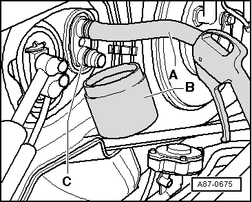
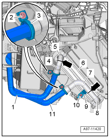
| – |
Push a piece of hose -A- onto
upper connection. |
| Insert compressed air gun into end of hose. |
| – |
Hold drip tray -B- under
connection -C- and carefully blow
coolant out of heat exchanger using compressed air gun. |
| – |
Seal off open lines and connections with clean plugs from
engine bung set -VAS 6122-. |
| – |
Remove driver side knee airbag
→ General body repairs, interior; Rep. gr.69. |
| – |
Remove left centre console trim in footwell
→ General body repairs, interior; Rep. gr.68. |
| – |
Vehicles with auxiliary air heater: Remove auxiliary air
heater element -Z35- with auxiliary air heater control unit
-J604-
→ Chapter. |
| – |
Cover area beneath connections for coolant hoses in plenum
chamber as well as airbag control unit -J234- with, for example,
impermeable sheeting and absorbent paper. |
|
|
|
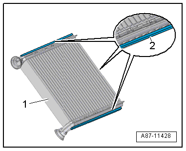
| – |
Check the foam seals -2-
attached to the heat exchanger -1-
for damage and replace if necessary. |
Note
| If the foam seal is not bonded in, it may roll up when the
heat exchanger is fitted. |
| If the foam seal is damaged or improperly fitted, cold air
can flow past the heat exchanger. |
| The illustration shows the heat exchanger for a “Valeo”
heater and air conditioning unit. |
|
|
|
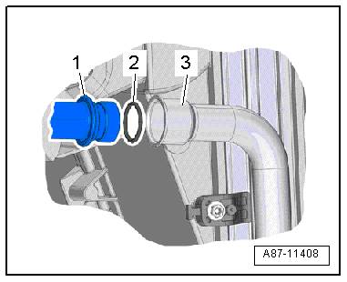
| – |
Check connection -3- of the
heat exchanger and the connection of the coolant pipes
-1- for damage or dirt. |
| – |
Clean and smoothen sealing surface for seals. |
| – |
Moisten new seals -1- with
coolant (or lubricate lightly with silicone grease) and fit them
to coolant pipe. |
| – |
Carefully slide heat exchanger into heater and air
conditioning unit as far as stop. |
Note
| When sliding in the heat exchanger, make sure not to damage
the connections and coolant pipes. |
| – |
Push coolant pipes into heat exchanger as far as stop. |
Risk of malfunction on heat exchanger due to defective seals and
leaks.Never squeeze seals.Never cant coolant pipes.Slide on coolant
pipes completely. |
|
|
| – |
Fit heat exchanger bracket -3-
on air distribution housing and tighten bolt
-4- to specified torque. |
| – |
Fit new clip -2- to joint
between coolant pipe and heat exchanger. |
| – |
Tighten bolt -1-
→ Chapter „Assembly overview - heater and air conditioning unit“. |
| – |
Check clip and screw-type clip for proper seating on
connections of heat exchanger and check coolant pipes. The
coolant pipes must not contact air distribution housing or any
other components. |
| – |
Fill with coolant
→ Rep. gr.19. |
| – |
Read event memory, and clear any entries displayed vehicle
diagnostic tester in “Guided fault finding” mode. |
| – |
As a final step, check operation of heater and air
conditioner. |
| → Chapter „Assembly overview - heater and air conditioning unit“ |
| Turbocharger; Assembly overview - turbocharger
→ Rep. gr.21. |
| Centre console; Assembly overview - centre console
→ General body repairs, interior; Rep. gr.68 |
| Knee airbags; Assembly overview - knee airbag
→ General body repairs, interior; Rep. gr.69. |
|
|
|
Special tools and workshop equipment
required
Drip tray for workshop hoist -VAS 6208-
& ...
Special tools and workshop equipment
required
Drip tray for workshop hoist -VAS 6208-
& ...
Other materials:
Drink holders in the rear centre armrest
Fig. 120 Drink holder in rear centre armrest:
examples of ways to adjust drink holder for different purposes
Fig. 121 Drink holders in the rear centre
armrest
First read and observe the introductory information
and safety warnings
To open, fold the centre armrest down.
To close ...
Introduction
This chapter contains information on the following subjects:
→ Drink holders in the front centre console
→ Drink holders in the rear centre armrest
→ Drink holder in the rear side trim
Bottle holder
Bottle holders are located in the open stowage areas of t ...
Removing and installing emblem with model designation, “R”
Special tools and workshop equipment
required
Torque wrench -V.A.G 1783-
Note
Only remove when radiator grille -3- is
removed.
Removing
...
© 2016-2026 Copyright www.vwgolf.org

 Removing and installing Valeo heat exchanger, RHD vehicles
 Removing and installing Denso heat exchanger, RHD vehicles