Volkswagen Golf Service & Repair Manual: Removing and installing defroster flap control motor -V107- with
potentiometer -G135-, LHD vehicles
| Special tools and workshop equipment
required |
| Vehicle diagnostic tester |
| First carry out the following work: |
| – |
Switch off all electrical consumers. |
| – |
Remove glove compartment
→ General body repairs, interior; Rep. gr.68. |
|
|
|
| – |
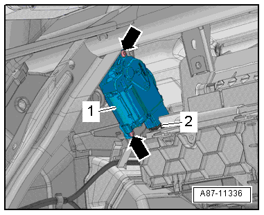
Unscrew bolts -arrows-. |
| – |
Remove defroster flap control motor -V107--1-. |
| – |
Disconnect electrical connector -2-. |
| Installation is carried out in the reverse order. When
installing, note the following: |
 Note Note
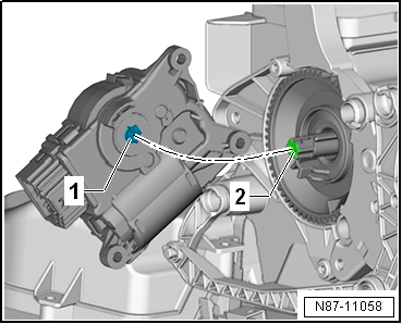
| Check operation of flaps and hinge mechanism before fitting. |
| Make sure levers and shafts are properly fitted in the
mounts. |
|
|
|
Heater and air conditioning system with electric/manual
controls
Special tools and workshop equipment
required
Veh ...
Special tools and workshop equipment
required
Vehicle diagnostic tester
First carry out the following work:
...
Other materials:
Catalytic converter
First read and observe the introductory information
and safety warnings The catalytic converter is used for exhaust gas post-treatment
and helps to reduce exhaust emissions. To help ensure long-term functionality in
the exhaust system and the catalytic converter:
Use unleaded petrol onl ...
Vehicle diagnostic, testing and information systems
WARNING
During testing or measuring operations using a
vehicle diagnostic information system there is a risk of
serious or even fatal injury!
If the vehicle diagnost ...
Removing and installing evaporator temperature sensor -G308-, LHD vehicles
Special tools and workshop equipment
required
Removal wedge -3409-
Note
Only vehicles with air conditioning system; on vehicles with
heater, opening in heater ...
© 2016-2026 Copyright www.vwgolf.org

 Removing and installing temperature flap control motor - V68-, RHD vehicles
 Removing and installing defroster flap control motor -V107- with
potentiometer -G135-, RHD vehicles
Removing and installing defroster flap control motor -V107- with
potentiometer -G135-, RHD vehicles