Volkswagen Golf Service & Repair Manual: Removing and installing brake master cylinder, RHD vehicles
| Special tools and workshop equipment
required |
|
|
|
| Torque wrench -V.A.G 1331- |
|
|
|
| Torque wrench -V.A.G 1410- |
| Tool inserts (11 mm) -V.A.G 1331/2- |
|
|
|
| Brake filling and bleeding equipment -VAS 5234- |
|
|
|
| Sealing plug repair kit -1H0 698 311 A- |
| Hot air blower, e.g. hot air blower -VAS 1978/14A- |
|
|
|
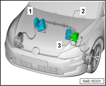
| The brake master cylinder is located on right-hand side of
the engine compartment. |
| 1 - |
Brake servo and brake master cylinder |
| 2 - |
Brake system pressure accumulator -VX70- |
| 3 - |
ABS control unit -J104- with ABS hydraulic unit -N55- |
| Make sure not to bend the brake lines in the area of the
brake master cylinder. |
| – |
Observe safety precautions when working on the high-voltage
system
→ Chapter. |
| – |
Observe the risk classification of the high-voltage system
→ Electric drive; Rep. gr.00. |
| – |
Disconnect battery
→ Electrical system; Rep. gr.27. |
| – |
Remove engine cover
→ Rep. gr.10. |
|
|
|
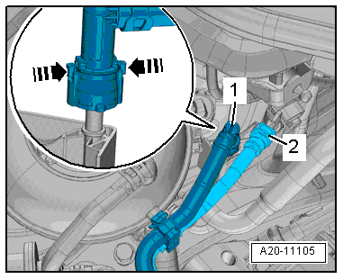
| – |
Disconnect fuel lines -1- and
-2- and lay to side. Separate
plug-in connectors
→ Rep. gr.20. |
|
|
|
| Vehicle with heat shield: |
| – |
Detach heat shield -2- at top
of brake fluid reservoir -3--arrows-. |
| Continuation for all models: |
| – |
Place sufficient lint-free cloths in area of engine,
subframe and gearbox. |
|
|
|
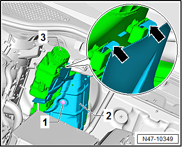
| – |
Release and disconnect connector -2-
from brake fluid level warning contact -F34- at brake fluid
reservoir -1-. |
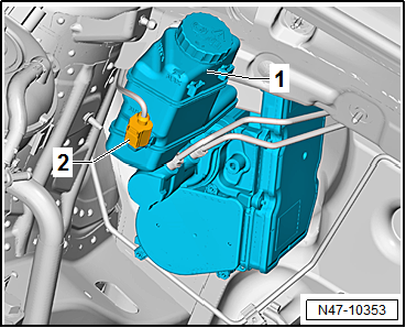
| – |
Draw off as much brake fluid as possible from brake fluid
reservoir using brake filling and bleeding equipment -VAS 5234-. |
|
|
|
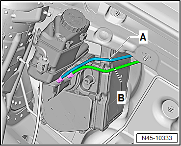
| – |
Mark brake lines -A- and
-B- on brake master cylinder. |
| – |
Unscrew brake lines -A- and
-B- from brake master cylinder. |
| – |
Immediately seal brake lines and open connections with
sealing plugs from repair kit -1H0 698 311 A- or suitable plugs
from engine bung set -VAS 6122-. |
|
|
|
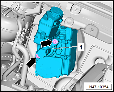
| – |
Remove brake master cylinder -1-
from brake servo. |
| Install in reverse order. Note the following points: |
| – |
When assembling brake master cylinder with brake servo, make
sure push rod is properly positioned in brake master cylinder. |
| – |
When joining brake master cylinder to brake servo, make sure
seal is properly seated. |
| – |
Bleed brake system
→ Chapter. |
| – |
Subsequently bleeding the brake system
→ Chapter. |
| – |
Perform basic setting for electromechanical brake servo
→ Vehicle
diagnostic tester. |
| → Chapter „Assembly overview – Brake system pressure accumulator
-VX70-, RHD vehicles“ |
| → Heating, air conditioning system; Rep. gr.87. |
|
|
|
Special tools and workshop equipment
required
Torque wrench -V.A.G 1331-
...
Special tools and workshop equipment
required
Torque wrench -V.A.G 1331-
...
© 2016-2026 Copyright www.vwgolf.org

 Removing and installing brake master cylinder, LHD vehicles
 Removing and installing brake system pressure accumulator -VX70-, LHD
vehicles
Removing and installing brake system pressure accumulator -VX70-, LHD
vehicles