Volkswagen Golf Service & Repair Manual: Removing and installing brake system pressure accumulator -VX70-, LHD
vehicles
| Special tools and workshop equipment
required |
|
|
|
| Torque wrench -V.A.G 1331- |
|
|
|
| Torque wrench -V.A.G 1410- |
| Tool inserts (11 mm) -V.A.G 1331/2- |
|
|
|
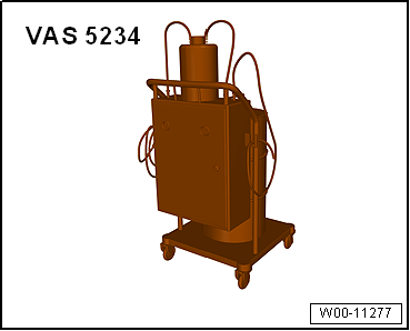
| Brake filling and bleeding equipment -VAS 5234- |
|
|
|
| Sealing plug repair kit -1H0 698 311 A- |
|
|
|
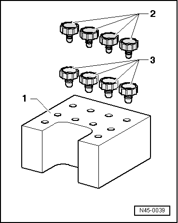
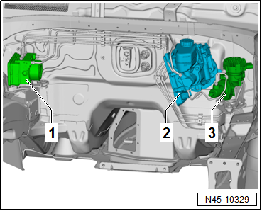
| 2 - |
Brake servo and brake master cylinder |
| 3 - |
Brake system pressure accumulator -VX70- |
| – |
Observe safety precautions when working in the area of
high-voltage components
→ Chapter. |
| – |
Observe the risk classification of the high-voltage system
→ Electric drive; Rep. gr.00. |
|
|
|
| Danger to life due to high voltage |
| The high-voltage system is under high voltage. If high-voltage
components are damaged, there is a risk of severe or fatal injury due to
electric shock. |
| – |
Carry out visual inspection of high-voltage components and cables. |
| – |
Never use cutting or forming tools, or any others with sharp edges. |
| – |
Never use heat sources such as welding, soldering, thermal bonding
or hot air. |
| – |
Disconnect battery
→ Electrical system; Rep. gr.27. |
| – |
Remove power and control electronics for electric drive
-JX1-
→ Electrical system; Rep. gr.93. |
| – |
Remove bracket for power and control electronics for
electric drive -JX1-
→ Electrical system; Rep. gr.93. |
| – |
Draw off as much brake fluid as possible from brake fluid
reservoir using brake filling and bleeding equipment -VAS 5234-. |
| – |
Place sufficient lint-free cloths in the area of the brake
system pressure accumulator -VX70--1-. |
|
|
|
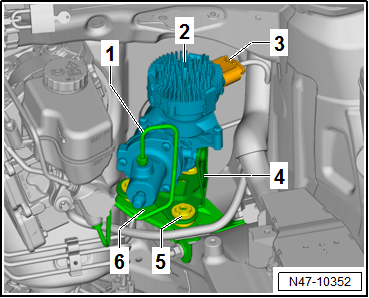
| – |
Unscrew brake line -1- from
brake system pressure accumulator -VX70--2-. |
| – |
Seal threaded hole immediately using sealing plugs -1H0 698
311 A-. |
| – |
Fit a dust cap from the bleeder valve onto brake line. |
| – |
Pull brake system pressure accumulator -VX70--2-
together with bracket -4- and
rubber dampers -5- upwards off
bracket -6-. |
| – |
Slightly tilt brake system pressure accumulator -VX70-, then
release and pull off connector -3-. |
| Install in reverse order. Note the following points: |
|
|
|
| – |
Ensure rubber dampers -5- are
seated correctly in bracket -4- of
brake system pressure accumulator -VX70-. |
| – |
Ensure that retaining pins have been fully and evenly
inserted into rubber dampers. |
| – |
Ensure secure seating by pulling. |
| Ensure that rubber dampers of retainer are not pressed out
of bracket when installing. After installation, check that the
brake system pressure accumulator -VX70- is securely seated,
otherwise malfunction can occur. |
| – |
Bleed brake system
→ Chapter. |
| – |
Subsequently bleeding the brake system
→ Chapter. |
| – |
Perform basic setting for electromechanical brake servo
→ Vehicle
diagnostic tester. |
| → Chapter „Assembly overview - brake servo/brake master
cylinder, LHD vehicles“ |
| → Chapter „Assembly overview – Brake system pressure accumulator
-VX70-“ |
| → Electrical system; Rep. gr.93 |
| → Electrical system; Rep. gr.27. |
|
|
|
Special tools and workshop equipment
required
Torque wrench -V.A.G 1331-
...
Special tools and workshop equipment
required
Torque wrench -V.A.G 1331-
...
Other materials:
Separating cover and padding for rear seat backrest
Special tools and workshop equipment
required
Upholstery clip pliers -V.A.G 1634
Removing
–
Remove backrest cover with bac ...
Rolling resistance optimised tyres
The energy loss caused by the deformation of the tyre when
rolling is known as rolling resistance.
With rolling resistance optimised tyres the deformation is
greatly reduced by a revised design and the use of optimised
tread compositions ...
Adjusting bonnet
Adjusting bonnet
Special tools and workshop equipment
required
Torque wrench -V.A.G 1331-
Note
Vehicle must be standing on its wheels to enable bonnet to ...
© 2016-2026 Copyright www.vwgolf.org

 Removing and installing brake master cylinder, RHD vehicles
 Removing and installing brake system pressure accumulator -VX70-, RHD
vehicles
Removing and installing brake system pressure accumulator -VX70-, RHD
vehicles