Volkswagen Golf Service & Repair Manual: Painting parking aid sensor
| To avoid malfunctions in the parking aid sensor, always
observe the following when painting: |
| |
Maximum layer thickness 125 µm; a measurement of layer depth
is absolutely essential following application of the paint |
| |
Maximum hardening temperature 1 hour at 90°C |
| |
Remove old finish (sand) only as far as the primer |
| |
Minimum layer depth of 5-10 µm must remain. |
| |
Maximum layer thickness 125 µm; a measurement of layer depth
is absolutely essential following application of the paint |
| |
Maximum hardening temperature 1 hour at 90°C |
| |
Do not allow paint or paint mist to enter connector;
connector pin must continue to provide electrical contact after
painting. |
| |
Immersion in cleaning solutions without previous masking of
the connector pins is prohibited. |
| |
Connect vehicle diagnostic tester, and check proper
operation
→ Electrical system, General information; Rep. gr.97. |
|
|

|
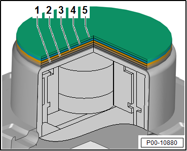
| Paintwork repair structure and layer depth |
| 1 - |
Primed new part with replacement part primer: 2-10 µm |
| 3 - |
Unicolour base coat: 10 - 20 µm |
| 4 - |
Base coat metallic/pearl effect: 20 - 25 µm |
| 5 - |
Clear coat: 35 - 50 µm |
|
|
|
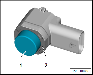
| 1 - |
Only the front and side faces of the sensor membrane are to
be painted. The painting area ranges from a minimum 3 mm to a
maximum 4 mm from the front face of the membrane towards the
rear. |
| 2 - |
No paint is permitted in this area. |
|
|
|
Attachments
Wings, doors, covers and flaps must be coated completely on
the inside as well. One wet-in-wet spray pass is adequate for
...
Note
On vehicles with ACC, the trim in the right-hand
cover of the front bumper must not be painted during a
repair paint j ...
© 2016-2026 Copyright www.vwgolf.org

 Corrosion protection for body components, add-on components and welded
components
Corrosion protection for body components, add-on components and welded
components ACC — Adaptive Cruise Control