Volkswagen Golf Service & Repair Manual: Lowering rear axle, multi-link suspension, front-wheel drive, except for
e-Golf
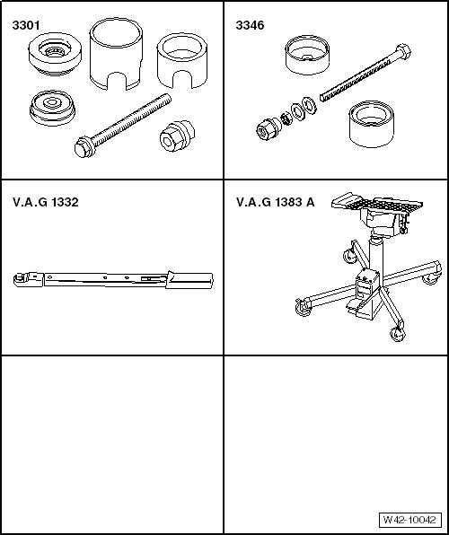
| Special tools and workshop equipment required |
| Torque wrench -V.A.G 1332- |
| Engine and gearbox jack -V.A.G 1383 A- |
| Lower subframe with attachments. |
| – |
Unbolt brake calipers on both sides of vehicle and suspend
from body. |
| – |
Remove springs
→ Chapter. |
| – |
Remove rear silencer of exhaust system
→ Rep. gr.26. |
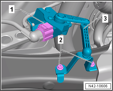
| Vehicles with vehicle level sender |
|
|
|
| – |
Disconnect connector -1-. |
| Continuation for all vehicles |
|
|
|
| – |
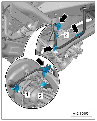
Unplug electrical connector -1-
from ABS speed sensor on both sides and move clear. |
| – |
Unplug electrical connector -2-
from electromechanical parking brake motor on brake caliper on
both sides. |
| – |
Detach electrical wiring harness from retainers
-arrows- and move clear. |
|
|
|
| – |
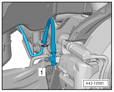
Pull out retaining clip -1- on
both sides of vehicle. |
| – |
Free brake lines from holder. |
 Note Note
|
|
|
| – |
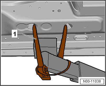
Use tensioning straps -T10038--1-
to strap vehicle to support beams of lifting platform on both
sides. |
 WARNING
| If the vehicle is not strapped down, there is a
great danger that the vehicle will slip off the lifting
platform! |
|
| – |
Fix subframe at both forward bolts
→ Chapter. |
|
|
|
| – |
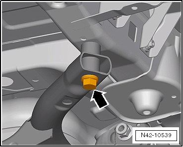
Unscrew rear right bolt of subframe
-arrow-. |
|
|
|
| – |
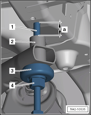
Screw spindle -3346/2- into thread of longitudinal member
using thrust piece of assembly tool -3301- and nut -3346/3-. |
| 3 - |
Thrust piece from assembly tool -3301- |
| – |
Unscrew rear left bolt of subframe. |
| – |
Turn nut -3346/3- on spindle -3346/2- until subframe is
lowered by -a- = 40 mm. |
| Installing subframe with attachments |
| Install in reverse order of removal, observing the
following: |
| → Chapter „Torque settings for wheel bolts“ |
| Exhaust pipes double clamp
→ Rep. gr.26. |
| On vehicles with vehicle level sender, carry out basic
settings for wheel damper electronics → Vehicle
diagnostic tester. |
| On vehicles with vehicle level sender, carry out basic
adjustment of headlights
→ Electrical system; Rep. gr.94. |
| – |
When does wheel alignment have to be checked
→ Chapter? |
|
|
|
I -
→ Chapter „Subframe“
II -
→ Chapter „Anti-roll bar“
III -
→ Chapter „Sus ...
Special tools and workshop equipment required
Assembly tool -3301-
Assembly tool -3346-
Torque wrench -V.A.G 1332-
...
Other materials:
Assembly overview - front vehicle level senders
Note
The front left/right vehicle level sender -G78/G289- is only
available as a replacement part complete with coupling rod and upper and
lower retaining plates.
1 -
Suspension link
2 -
Subframe
3&nbs ...
Vehicle lifting points
Fig. 205 Lifting point at front for the
lifting platform or vehicle jack
Fig. 206 Lifting points at rear for the
lifting platform or vehicle jack
First read and observe the introductory information
and safety warnings The vehicle may only be lifted at the points shown in
the illustrati ...
Calibrating Blind Spot Monitor control unit -J1086-/-J1087-
Note
Before the actual calibration process of the control units,
the calibration unit -VAS 6350- needs to be set up as described
in the following chapter.
Special tools and workshop equipment
required
...
© 2016-2026 Copyright www.vwgolf.org


 Overview - rear axle, multi-link suspension, four-wheel drive
 Lowering rear axle, multi-link suspension, front-wheel drive, e-Golf