Volkswagen Golf Service & Repair Manual: Calibrating Blind Spot Monitor control unit -J1086-/-J1087-
 Note Note
| Before the actual calibration process of the control units,
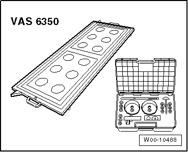
the calibration unit -VAS 6350- needs to be set up as described
in the following chapter. |
| Special tools and workshop equipment
required |
|
|
|
| Calibration unit -VAS 6350- |
| Vehicle diagnostic tester |
| During the calibration process the following should not
occur: |
| Vehicle doors should not be opened or closed. |
| There should be no-one in the vehicle. |
| No-one should pass through the space between the vehicle and
the calibration unit for lane change assist -VAS 6350/4-. |
|
|
|
| During the program sequence you will be requested to change
the calibration unit for lane change assist -VAS 6350/4- from
the left to the right-hand side of the calibration unit -VAS
6350-. |
| – |
Switch off the calibration unit for lane change assist -VAS
6350/4-, and change to the other side. |
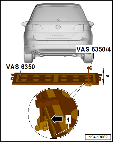
| If assembled correctly, the mains power lead should be
fitted to the bottom left of the calibration unit (as seen
facing direction of normal travel). |
| Dimension -a- = 606 mm
(measured from upper edge of calibration unit to floor). |
| Setting dimension right = 621 mm (read off from measuring
scale -1-). |
|
|
|
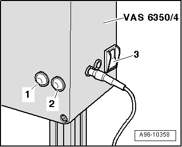
| – |
Switch on the calibration unit for lane change assist -VAS
6350/4- using the mains switch -3-. |
| The green LED -1- must light
up. |
| – |
Proceed by following the instructions on the display of
vehicle diagnostic tester. |
| Upon completion of lane change assist system calibration
switch off ignition and disconnect diagnosis connector. |
|
|
|
Extensive preliminary work is required before the actual
calibration can be carried out using → Vehicle
diagnostic tester.
Prerequis ...
Other materials:
Aquaplus system (pearlescent and heliochrome)
Designation:
Pearlescent waterborne base coat -LPW 040 ...-
Heliochrome waterborne base coat -LHW 046 ...-
Pearlescent waterborne mixing paint -LWM 076 ...-
Issued 11.2 ...
Removing and installing bulb for rear interior light -W43- with incandescent
bulbs
Special tools and workshop equipment
required
Removal wedge -3409-
Note
The lights used for the rear interior light -W43- are the
same as the rear left and rea ...
Displays
Fig. 172 In the instrument cluster display:
distance warning display
Fig. 173 The display in the instrument
cluster: advance warning display
First read and observe the introductory information
and safety warnings Distance warning
If the safe distance to the vehicle in front drops below ...
© 2016-2026 Copyright www.vwgolf.org

 Preparatory measures for calibration