Volkswagen Golf Service & Repair Manual: Preparatory measures for calibration
| Extensive preliminary work is required before the actual
calibration can be carried out using → Vehicle
diagnostic tester. |
| Position vehicle on a firm and level surface. |
| Apply parking brake – the vehicle must not be moved while
the calibration procedure is being performed. |
| Make sure steering wheel is at centre position with wheels
pointing straight ahead. |
| Nobody may be inside vehicle during measurement. |
| Opening and closing the vehicle doors during calibration
must be avoided. |
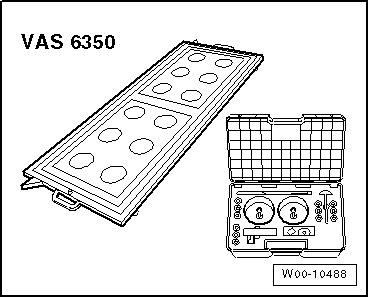
| Special tools and workshop equipment
required |
|
|
|
| Calibration unit -VAS 6350- |
| Vehicle diagnostic tester |
| – |
Connect vehicle diagnostic tester. |
|
|
|
| – |
Attach 3 wheel bolt adapters (spanner size 17) to each wheel
centre mounting -VAS 6350/1- for the wheel securing bolts. |
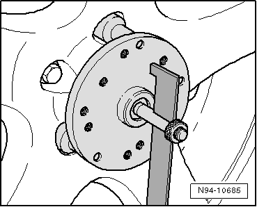
| – |
Insert measuring paddles in both wheel centre mountings -VAS
6350/1-, and secure them with clamping nut. |
| – |
Fit wheel centre mountings -VAS 6350/1- onto wheel bolts on
both rear wheels. |
| The turning centre of the wheel centre mounting must be in
the turning centre of the wheel. |
 Note Note
| Fit wheel centre mountings -VAS 6350/1- onto the wheels so
that the “anti-theft wheel bolts” are not connected to the wheel
centre mountings. |
| – |
Adjust measuring paddles with the help of the clamping nuts
in such a way that they can move freely just above the floor. |
| The measuring paddles must not be restricted in movement. |
| The measuring paddles must be vertical. |
|
|
|
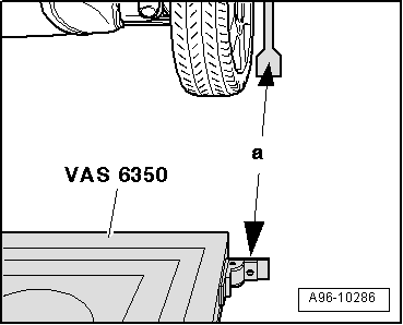
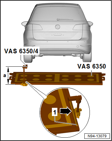
| – |
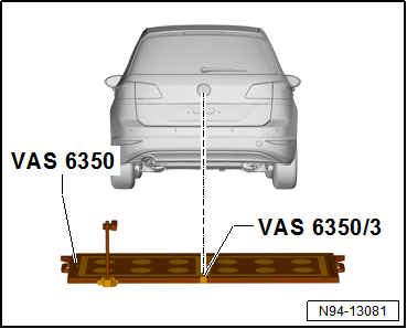
Position calibration unit -VAS 6350- at distance
-a- to rear wheels. |
| Dimension -a - = 1700 ± 2 mm |
|
|
|
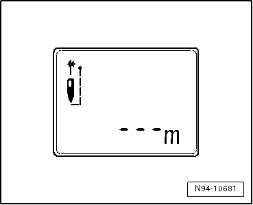
| – |
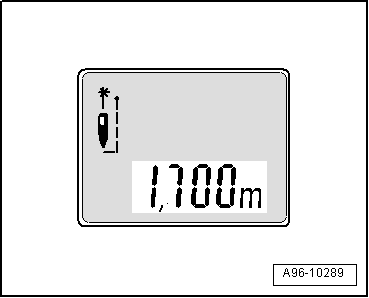
Push ON button to switch on
spacing laser -VAS 6350/2-. |
| Indicated on display of -VAS 6350/2-: |
Note
| The laser is switched on at the same time. |
|
|
|
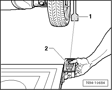
| – |
-VAS 6350/2- Hold spacing laser -2-
for distance measurement flush with stop bracket as shown in
illustration. |
| When doing this, make sure that spacing laser -VAS 6350/2-
is firmly in contact with stop bracket. |
| – |
Ensure that the “laser beam” for distance measurement is at
the bottom enlarged part on the measuring paddle
-1-. |
|
|
|
| If this is not the case, adjust height of measuring paddles
using lock nuts on wheel centre mountings -VAS 6350/1-. |
| – |
Now, briefly press ON button to
measure distance. |
| Indicated on display of -VAS 6350/2-: |
| “1.700 m” (specification: 1700 ± 2 mm). |
| – |
Repeat the measuring process from the left stop bracket to
the measuring paddle on the rear left wheel. |
| Measured distance value must be identical on both sides. |
| If both measured values are not identical, adjust
calibration unit -VAS 6350- accordingly. |
Note
| The vehicle shown in the illustration may differ from the
actual vehicle. |
|
|
|
| – |
Attach calibration unit for lane change assist -VAS 6350/4-
on rear left on mounting of calibration unit -VAS 6350-. |
| If assembled correctly, the mains power lead should be
fitted to the bottom left of the calibration unit (as seen
facing direction of normal travel). |
| Dimension -a- = 606 mm
(measured from upper edge of calibration unit to workshop
floor). |
| – |
The dimension is set with the measuring point
-arrow- at the base of the
calibration unit on the scale of the steel rule
-1-. |
| Setting dimension left = 621 mm (read off on measuring scale
-1-). |
| – |
Connect the calibration unit for lane change assist -VAS
6350/4- to mains voltage. |
|
|
|
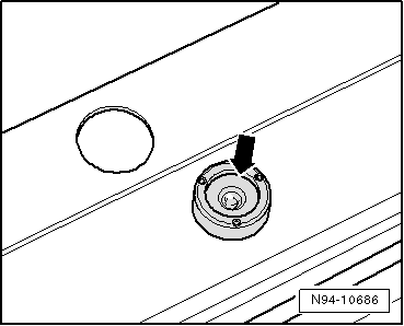
| – |
Bring the calibration unit -VAS 6350- to the horizontal
position with the aid of the vial (sight glass)
-arrow- by turning the plastic
feet. |
|
|
|
| – |
Wear laser safety goggles. |
Note
| The vehicle shown in the illustration may differ from the
actual vehicle. |
| – |
Switch on linear laser -VAS 6350/3- on calibration unit -VAS
6350-. |
| – |
Align the whole calibration unit -VAS 6350- so that the
laser beam is focused on the rear of the vehicle in the centre
above the VW badge. |
|
|
|
| – |
Check the spacing on the left and right again between the
stop brackets of the calibration unit -VAS 6350- and the
measuring paddles -1- on the wheel
mountings. |
| Specification: 1700 ± 2 mm |
| Calibrating lane change assist control unit
→ Chapter. |
|
|
|
Note
The vehicle shown in the illustration may differ from the actual
vehicle.
1 -
Volkswagen logo
Laser pointer aligned to cent ...
Note
Before the actual calibration process of the control units,
the calibration unit -VAS 6350- needs to be set up as described
in the following chapt ...
Other materials:
Removing and installing intermittent wiper switch -E22-
Note
The turn signal switch -E2-, cruise control system switch
-E45- and intermittent wiper switch -E22- are combined to form
the steering column combination switch -E595-.
These switches cannot be separated.
...
Specified values for wheel alignment, multi-link suspension, Golf
These specifications apply to all engines.
Explanations regarding PR numbers
→ Chapter „Vehicle data sticker“.
Front axle
Basic
running gear
Sports
running gear
Raised
running gear
DCC
running gear
...
Assembly overview - rear side airbag
1 -
Seat bolster
2 -
Electrical wiring
From rear side airbag igniter on driver side -N201-/rear side airbag
igniter on front passenger side -N202-
WARNING
Observe safety instructions for pyrote ...
© 2016-2026 Copyright www.vwgolf.org

 Measurement location
 Calibrating Blind Spot Monitor control unit -J1086-/-J1087-