Volkswagen Golf Service & Repair Manual: Renewing bonded rubber bush for axle beam
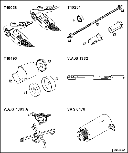
| Special tools and workshop equipment required |
| Tensioning strap -T10038- |
| Torque wrench -V.A.G 1332- |
| Engine and gearbox jack -V.A.G 1383 A--2-
with gearbox support -V.A.G 1359/2-. |
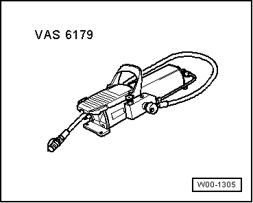
| Hydraulic press -VAS 6178- and press button -10205/13- |
| Vehicles with vehicle level sender |
|
|
|
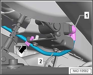
| – |
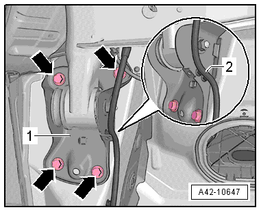
Release and pull off connector -1-
on rear left vehicle level sender -G76-. |
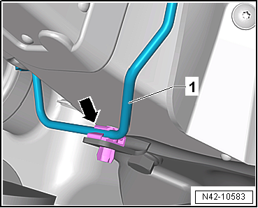
| – |
Unclip line -2- from clip
-arrow-. |
|
|
|
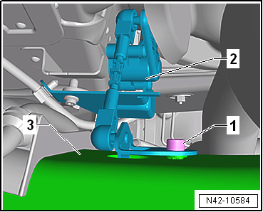
| – |
Pull rear left -G76- lever -2-
off axle beam -3-. |
| Continuation for all vehicles |
|
|
|
| – |
Unclip brake line -1- from clip
-arrow- on right mounting bracket. |
 Note Note
| The clip will be destroyed and must be renewed. |
|
|
|
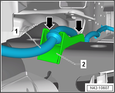
| – |
Unclip electric cable -1- from
both sides -arrows- of retainer
-2- on axle beam. |
|
|
|
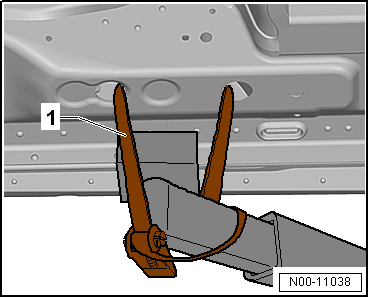
| – |
Use tensioning straps -T10038--1-
to strap vehicle to support beams of lifting platform on both
sides. |
 WARNING
| If the vehicle is not strapped down, there is a
great danger that the vehicle will slip off the lifting
platform! |
|
|
|
|
| – |
Remove bolt -1- on left and
right. |
| – |
Position engine and gearbox jack -V.A.G 1383 A- with
universal gearbox support -V.A.G 1359/2- and suitable support
underneath. |
| – |
Unclip line -2- from mounting
bracket -1-. |
| – |
Mark positions of bolts -arrows-
on mounting bracket -1- on both
sides of vehicle. |
|
|
|
| – |
Unscrew bolts -1- for right and
left axle bodies. |
|
|
|
| – |
Carefully lower rear axle with engine and gearbox jack -V.A.G 1383 A-
until bolt -1- can be removed. |
|
|
|
| – |
Fit special tools as shown in illustration. |
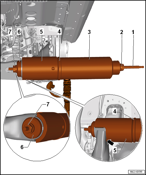
| 3 - Hydraulic press -VAS 6178- and thrust piece -T10205/13- |
| 4 - Thrust plate -T10495/3- |
| Make sure that the tube is lying against the axle beam
-arrow-. |
| 6 - Thrust piece -T10495/1- |
| – |
Pull out bonded rubber bush by operating the pump. |
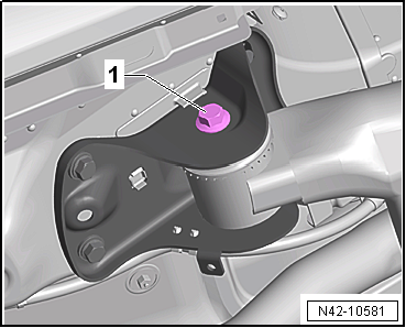
| – |
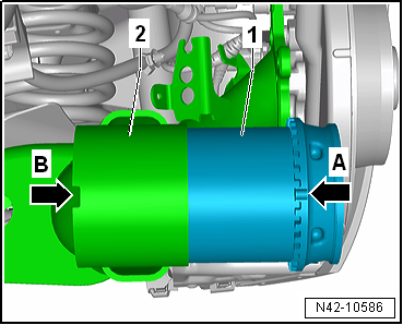
Ensure correct installation position of bonded rubber bush
-1- on axle beam
-2-. |
| Lug -arrow A- of bonded rubber
bush -1- must point towards lug
-arrow B- of axle beam
-2-. |
|
|
|
| – |
Fit special tools as shown in illustration. |
| 3 - Hydraulic press -VAS 6178- and thrust piece -T10205/13- |
| 4 - Thrust piece -T10495/1- |
| 6 - Thrust plate -T10495/3- |
| – |
Before pressing in bonded rubber bush, make sure that marking on
bonded rubber bush aligns with mark on axle beam. |
| – |
Press bonded rubber bush in to stop. |
| – |
After mounting, check installed position of bonded rubber bush. |
| Continue installation in reverse order. |
| → Chapter „Assembly overview - axle beam“ |
| → Chapter „Assembly overview - rear vehicle level sender,
torsion beam axle“ |
| → Chapter „Torque settings for wheel bolts“ |
| On vehicles with vehicle level sender, carry out basic
settings for wheel damper electronics → Vehicle
diagnostic tester. |
| On vehicles with vehicle level sender, carry out basic
adjustment of headlights
→ Electrical system; Rep. gr.94. |
|
|
|
1 -
Cover
2 -
Bolt
Renew after removing
50 Nm +45°
3 -
Bolt
...
© 2016-2026 Copyright www.vwgolf.org

 Assembly overview - axle beam
 Subframe