Volkswagen Golf Service & Repair Manual: Renewing bonded rubber bush

| Special tools and workshop equipment required |
| Tensioning strap -T10038- |
| Engine and gearbox jack -V.A.G 1383 A- |
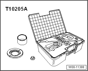
| Hydraulic press -VAS 6178- and thrust piece -T10205/13- |
 Note Note
| When a bonded rubber bush is defective, the bonded rubber
bush on the opposite side must also be renewed; allocation
→ Electronic Parts Catalogue “ETKA.”. |
| Before replacing a defective bonded rubber bush, check the
other bonded rubber bushes. |
| If cracks or other damage is visible, these bonded rubber
bushes must be renewed also. |
| To renew bonded rubber bushes, the subframe must be lowered
at the front or the rear. The removal of the subframe is not
required. |
| Mark position of bonded rubber bushes in relation to
subframe before removing. |
| Pressing out front bonded rubber bush |
| – |
Remove spring
→ Chapter. |
| – |
Remove rear silencer of exhaust system
→ Rep. gr.26. |
|
|
|
| – |
Pull out retaining clip -1- on
both sides of vehicle. |
Note
|
|
|
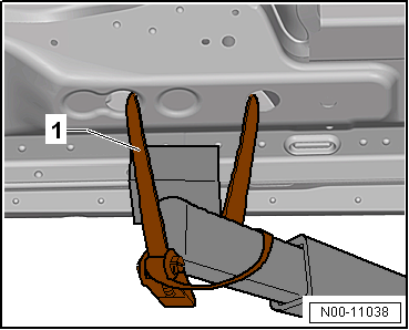
| – |
Use tensioning straps -T10038--1-
to strap vehicle to support beams of lifting platform on both
sides. |
 WARNING
| If the vehicle is not strapped down, there is a
great danger that the vehicle will slip off the lifting
platform! |
|
| – |
Fix position of subframe
→ Chapter. |
|
|
|
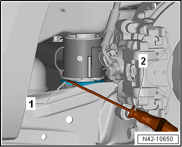
| – |
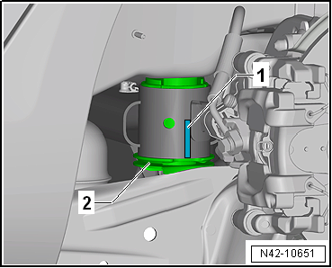
Mark installation position of bonded rubber bush in relation
to subframe with e.g. a felt-tip pen -1-. |
Note
| Make a mark -1- on subframe
centred on cut-out in bonded rubber bush
-2-. |
|
|
|
| – |
Lever anti-twist device -1- off
bonded rubber bush near retaining lug using, for example, a
screwdriver -2-. |
| – |
Lower subframe approx. 100 mm using engine and gearbox jack
-V.A.G 1383 A-. |
|
|
|
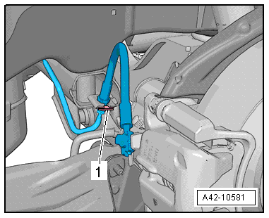
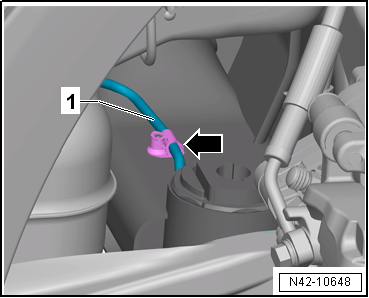
| – |
Unclip brake line -1- from clip
-arrow- on left side. |
Note
| The clip will be destroyed and must be renewed. |
|
|
|
| – |
Fit special tools as shown in illustration. |
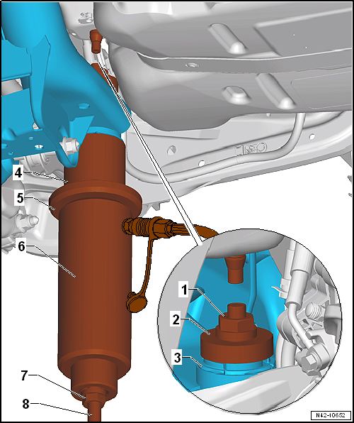
| 1 - Hexagon nut -T10263/5- |
| 2 - Thrust piece -T10356/1- |
| 4 - Tube -T10356/2-, side with recess faces subframe. |
| 5 - Thrust plate -T10205/1- |
| 6 - Hydraulic press -VAS 6178- and thrust piece -T10205/13- |
| 7 - Hexagon nut -T10263/5- |
| 8 - Threaded spindle -T10263/4- |
| – |
Take up play in special tools. |
| – |
Press out bonded rubber bush. |
Note
| The collar of the outer ring of the bonded rubber bush will be
sheared off by the mounting when the bush is pulled out. This occurs
with a loud bang. |
| After the bush has been pulled out, the collar must be removed from
the tube -T10356/2- with light hammer blows. |
| Pressing in front bonded rubber bush |
|
|
|
| – |
As an assembly aid, draw a line -1-
on the vertical rib of the bonded rubber bush. |
|
|

|
| – |
Coat outer edge of bonded rubber bush with assembly paste -G 294 421
A1-. |
| – |
Set up special tools with bonded rubber bush on subframe as shown. |
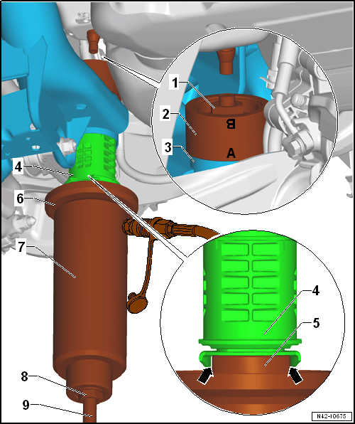
| 1 - Hexagon nut -T10263/5- |
| 2 - Thrust piece -T10356/7- - the marking -A-
faces towards subframe |
| 4 - Align bonded rubber bush on mark, made for this purpose (the
marks must align with one another) |
| 5 - Thrust piece -T10356/8- - the flattened sides must engage in
cover of bonded rubber bush -arrows-. |
| 6 - Thrust plate -T10205/1- |
| 7 - Hydraulic press -VAS 6178- and thrust piece -T10205/13- |
| 8 - Hexagon nut -T10263/5- |
| 9 - Threaded spindle -T10263/4- |
| – |
Check position of bonded rubber bush, realign if necessary
and preload bonded rubber bush using special tools. |
Note
| Ensure that the hose from the hydraulic cylinder -VAS 6178-
to the foot pump -VAS 6179- is routed between the trailing arm
and the fuel tank while pressing in the bush. |
| Ensure that the bonded rubber bush does not cant at the
start of the pressing action. Otherwise, the outer ring could be
damaged. |
| – |
Operate pump to press bonded rubber bush in until collar
lies »flush« on subframe. |
| Install in reverse order of removal, observing the
following: |
| → Chapter „Assembly overview - subframe, multi-link suspension,
four-wheel drive“ |
| → Chapter „Torque settings for wheel bolts“ |
| Exhaust system
→ Rep. gr.26 |
|
|
|
Special tools and workshop equipment
required
Locating pins -T10096-
...
Special tools and workshop equipment required
Tensioning strap -T10038-
Assembly tool -T10263-
Assembly tool -T10356-
E ...
© 2016-2026 Copyright www.vwgolf.org

 Fixing position of subframe, multi-link suspension, four-wheel drive
 Renewing rear bonded rubber bush