Volkswagen Golf Service & Repair Manual: Renewal of aerial wiring
| A new approach to repair work on aerial wires has been
developed
→ Chapter. |
| Now connecting wires in different lengths and various
adapter cables are available as replacement parts instead of a
complete aerial wire. |
| Replacement parts can be found in the
→ Parts catalogue (ETKA): Special catalogue; Electrical
connections; Genuine accessories; Subgroup 35 from illustration
No. 035-20. |
| These genuine parts are suitable for all aerial wires and
wire diameters which may need to be replaced. |
| The connector housings for aerial wires are only available
as genuine parts in one colour. However, they can be used for
all colours of aerial connector. |
| No provision has been made for replacement of individual
aerial connectors in the event of repair. |
| The wires can be used retroactively for all VW models, with
all installed aerial wire diameters. |
| All adapter and connection wires are suitable for all
transmitter and receiver signals. |
| This repair method can also be used for testing or
retrofitting. |
|
|
|
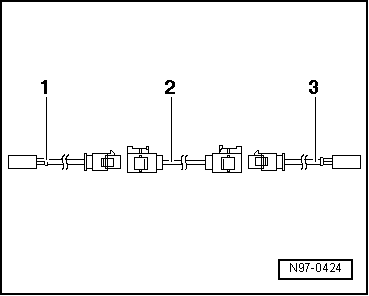
| Assembly overview of aerial cable: |
| Example: aerial wire between radio and aerial is defective.
The following wires are required for the repair: |
| 1 - |
Adapter cable, to radio connection. Length approx. 30 cm. |
| 2 - |
Connecting wire, available in different lengths. |
| 3 - |
Adapter cable, to aerial connection. Length approx. 30 cm. |
| Installing a new aerial cable: |
 Note Note
| Note that the total length of an aerial wire, depending on
vehicle equipment level, can be divided into sections by aerial
diversity control unit, traffic information control unit or
aerial amplifier. Only the defective section of aerial wire must
be replaced. |
| – |
Pull defective aerial wire connections off units. |
| – |
Determine the routing of the defective aerial wire in
vehicle and measure the total length of the aerial connecting
wire to be replaced. |
|
|
|
| The total length of aerial connecting wire is the sum of the
length of adapter cables required -1-
and -3- and the connecting wire
-2-. |
| – |
To determine the length of connecting wire required,
subtract 60 cm from the measured total length of aerial
connecting wire -2-. |
| – |
Procure the required adapter cables
-1- and -3- and connecting
wire -2- at length calculated as
genuine part from the Electronic parts catalogue (ETKA). |
| – |
Cut off connectors of defective aerial wire. |
| The remainder of the defective aerial wire remains in the
vehicle. |
| – |
Connect adapter cables -1- and
-3- to equipment in vehicle. |
| – |
Route and attach the connection line
-2- in the immediate vicinity of the factory routing. |
Note
| Do not kink or excessively bend aerial wires! The bending
radius must not be below 50 mm. |
| – |
Connect connecting wire to adapter cables. |
| – |
Perform functional test. |
|
|
|
An unshielded two-wire line -1-
and -2- with a cross section of
0.35 mm2 or 0.5 mm2
is used for CAN bus wiring.
The col ...
Special tools and workshop equipment
required
Crimping pliers, complete -VAS 1978/1 A-
...
© 2016-2026 Copyright www.vwgolf.org

 Repairs to CAN bus wiring
 Repairs to wiring with cross sections up to 0.35 mm2