Volkswagen Golf Service & Repair Manual: Removing and installing window regulator motor -V14-/-V15-
| Special tools and workshop equipment
required |
|
|
|
 Note
| |
Removal and installation are only described for the left
window regulator motor. Removal and installation of the right
window regulator motor are similar. |
| |
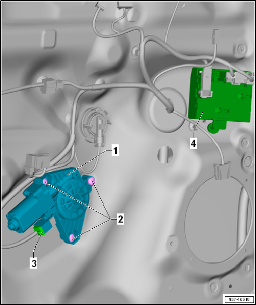
The door control unit -J386/J387--4-
is separated from window regulator motor -V14/V15--1-. |
| |
The door control unit -J386/J387- is clipped into door. |
|
|
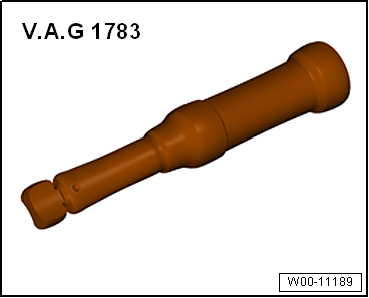
Torque wrench -V.A.G 1783- |
| – |
Remove front door trim
→ General body repairs, interior; Rep. gr.70. |
| – |
Secure door window against sliding down with adhesive tape. |
| – |
Switch off ignition and all electrical consumers. Remove ignition
key. |
| – |
Disconnect connector -3-. |
| – |
Remove bolts -2- (Qty. 3). |
| – |
Remove window regulator motor -1- from
mounting brackets of cable drum. |
 WARNING WARNING
| If a new window regulator motor (door control unit)
is installed, the additional functions and the excess force
limitation feature have to be coded! |
|
| – |
Position window regulator motor -1- on
mounting brackets of cable drum. Move door window up and down slightly
so that the splines between window regulator motor and cable drum engage
more easily. |
| – |
A new window regulator motor must be coded using
→ Vehicle
diagnostic tester. |
| – |
The work procedure and notes on the automatic window raising and
lowering system as well as on the excess-force limitation feature can be
found in
→ Booklet. |
| Further installation is performed in the reverse order of removal. |
| |
Bolts
→ Chapter „Assembly overview - window regulator“ |
Note
Only the left side is shown. The right side is similar.
1 -
Door lock
Removing and installing
→ Chapter
2 ...
Special tools and workshop equipment
required
Note
Removal and ...
Other materials:
Drink
holders in the front centre console
Fig. 118 In the lower part of the centre
console: opening the drink holder
Fig. 119 In the lower part of the centre
console: closing the front drink holder
First read and observe the introductory information
and safety warnings There are various versions of the drink holder in the
fron ...
Side view
Fig. 1 Overview of the driver side
Key for :
Roof aerial
Tank flap
Exterior door release lever
Exterior mirrors
Additional turn signal
Surround lighting
Jacking points
...
Checklist
In some countries, special safety standards and emissions-related
legislation apply that may differ from the construction of the vehicle. Volkswagen
recommends that you visit your Volkswagen dealership before travelling abroad
to find out about any legal requirements and the following is ...
© 2016-2026 Copyright www.vwgolf.org

 Assembly overview - door handle and door lock
 Removing and installing window regulator