Volkswagen Golf Service & Repair Manual: Removing and installing wheel bearing housing, multi-link suspension,
front-wheel drive
| Special tools and workshop equipment
required |
|
|
|
| Torque wrench -V.A.G 1332- |
|
|
|
| Engine and gearbox jack -V.A.G 1383 A- |
| – |
Remove wheel bearing unit
→ Chapter |
| – |
Remove heat shield
→ Brake system; Rep. gr.46. |
| – |
Remove spring
→ Chapter. |
| Vehicles with vehicle level sender |
|
|
|
| – |
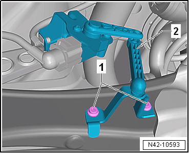
Remove retainer for rear left vehicle level sender-2-. |
| Vehicles with stone guard |
|
|
|
| – |
Remove spreader rivet -1-. |
| – |
Unscrew bolts -2- for stone
deflector -3-. |
| Continuation for all vehicles |
| – |
Disconnect electrical connector from ABS speed sensor and
electromechanical parking brake motor. |
|
|
|
| – |
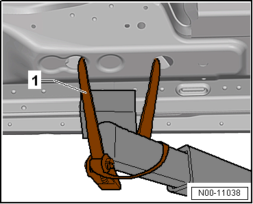
Use tensioning straps -T10038--1-
to strap vehicle to support beams of lifting platform on both
sides. |
 WARNING
| If the vehicle is not strapped down, there is a
great danger that the vehicle will slip off the lifting
platform! |
|
|
|
|
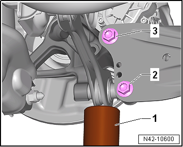
| – |
Position engine and gearbox jack -V.A.G 1383 A--1-
under track rod and press upwards slightly. |
| – |
Unscrew bolts -2- and
-3- one after the other. |
| – |
Remove engine and gearbox jack -V.A.G 1383 A--1-
from under track rod. |
|
|
|
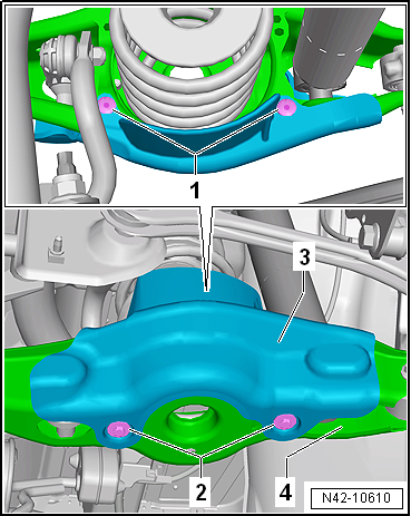
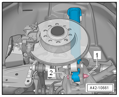
| – |
Unscrew nut -1- and remove bolt
-2-. |
|
|
|
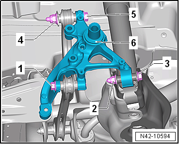
| – |
Undo nut -2- and pull out bolt
-3-. |
| – |
Undo nut -4-, remove washer and
pull out bolt -5-. |
| – |
Take out wheel bearing housing -6-. |
| Install in reverse order of removal, observing the
following: |
| It is essential to follow specified sequence of work steps
below! |
|
|
|
| – |
Insert wheel bearing housing -6-. |
| – |
Insert bolt -5- and washer and
tighten nut -4- only hand-tight. |
| – |
Insert bolt -3- and tighten nut
-2- only hand-tight. |
| – |
Insert bolt -1- and tighten
only hand-tight. |
| – |
Position engine and gearbox jack -V.A.G 1383 A--1-
under track rod and press upwards slightly. |
|
|
|
| – |
Screw in bolts -2- and
-3- by hand. |
| – |
Remove engine and gearbox jack -V.A.G 1383 A--1-
from under track rod. |
| – |
Install heat shield
→ Brake system; Rep. gr.46. |
| – |
Install wheel bearing unit
→ Chapter |
| The threaded connections of the wheel bearing housing may
only be loosened and tightened in the unladen weight position
→ Chapter. |
|
|
|
| – |
Tighten nuts and bolts -1- to
-5-. |
| – |
Detach engine and gearbox jack -V.A.G 1383 A- with support
-T10149- from wheel hub. |
|
|
|
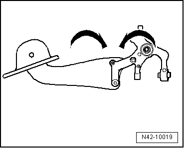
| Do not tighten bolts securing trailing arm to wheel bearing
housing until all other suspension components (especially spring
and shock absorber) on that side are fitted. To tighten, wheel
suspension must be in extended position. Only then do trailing
arm and wheel bearing housing move to the necessary position
-arrows-. |
| – |
Installing spring
→ Chapter. |
|
|
|
| – |
Tighten bolts -2- and
-3-. |
| → Chapter „Assembly overview - suspension, multi-link
suspension, front-wheel drive“ |
| → Chapter „Assembly overview - suspension strut, shock absorber,
spring, multi-link suspension“ |
| → Chapter „Assembly overview - trailing arm“ |
| → Chapter „Assembly overview - track rod“ |
| → Chapter „Assembly overview - rear vehicle level senders,
multi-link suspension, front-wheel drive“ |
| → Chapter „Torque settings for wheel bolts“ |
| Bolts for heat shield, brake caliper and brake disc
→ Brake system; Rep. gr.46 |
| On vehicles with vehicle level sender, carry out basic
settings for wheel damper electronics → Vehicle
diagnostic tester. |
| On vehicles with vehicle level sender, carry out basic
adjustment of headlights
→ Electrical system; Rep. gr.94. |
|
|
|
1 -
Cover
2 -
Bolt
Renew after removing
50 Nm +45°
3 -
Mounting bracket
...
Special tools and workshop equipment
required
Torque wrench -V.A.G 1332-
...
Other materials:
Mounting front seat on seat repair stand
Special tools and workshop equipment
required
Torque wrench -V.A.G 1331
Torque wrench -V.A.G 1783
...
Assembly overview - control units, RHD vehicles
1 -
Bracket
For onboard supply control unit -J519-
Removing and installing
→ Chapter
2 -
Onboard supply control unit -J519-
Removing and installing
→ Chapter
...
High-pressure sender -G65
This high-pressure sender -G65- is fitted in place of the
air conditioning system pressure switch -F129-.
When voltage is applied to the high-pressure sender, it
generates a square wave signal, or data telegram. This signal
changes when ...
© 2016-2026 Copyright www.vwgolf.org

 Assembly overview - trailing arm, except for e-Golf
 Removing and installing wheel bearing housing, multi-link suspension,
four-wheel drive
Removing and installing wheel bearing housing, multi-link suspension,
four-wheel drive