Volkswagen Golf Service & Repair Manual: Removing and installing Valeo heat exchanger, LHD vehicles
| Special tools and workshop equipment
required |
|
|
|
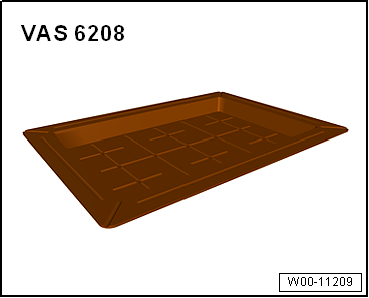
| Drip tray for workshop hoist -VAS 6208- |
|
|
|
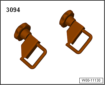
| Hose clamps up to 25 mm -3094- |
| Compressed air gun, commercially available |
|
|
|
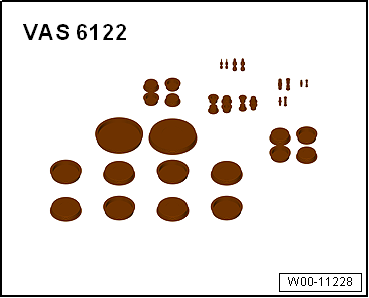
| Engine bung set -VAS 6122- |
| – |
Heed the safety precautions
→ Chapter „Safety instructions“. |
|
|
|
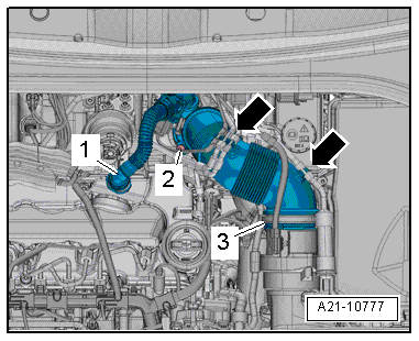
| Vehicles with TDI engine: |
| – |
Press release buttons on crankcase breather hose
-1- and detach hose from cylinder
head cover. |
| – |
Detach vacuum hoses from air pipe
-arrows- to permit access. |
| – |
Remove bolt -2-, swivel air
pipe with connection rearwards and detach from turbocharger. |
| Continuation for all vehicles: |
|
|
|
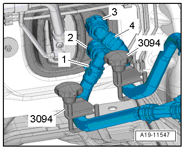
| – |
Mark installation position of coolant hoses
-1- and -4-. |
 Note Note
| The heat exchanger is designed for a particular direction of
flow of the coolant. Therefore, the coolant hoses must not be
interchanged when connecting them. |
| – |
Clamp off coolant hoses -1- and
-4- using hose clamps, up to 25 mm
-3094-. |
| – |
Lift retaining clips -2- and
-3-. |
| – |
Disconnect coolant hoses -1-
and -4- from heat exchanger for
heater. |
|
|
|
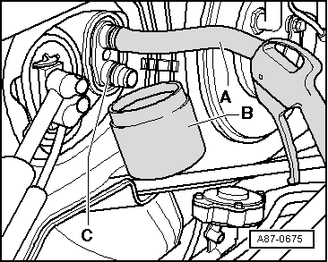
| – |
Push a piece of hose -A- onto
upper connection. |
| Insert compressed air gun into end of hose. |
| – |
Hold drip tray -B- under
connection -C- and carefully blow
coolant out of heat exchanger using compressed air gun. |
| – |
Seal off open lines and connections with clean plugs from
engine bung set -VAS 6122-. |
| – |
Remove driver side knee airbag
→ General body repairs, interior; Rep. gr.69. |
| – |
Remove left centre console trim in footwell
→ General body repairs, interior; Rep. gr.68. |
| – |
Vehicles with auxiliary air heater: Remove auxiliary air
heater element -Z35- with auxiliary air heater control unit
-J604-
→ Chapter. |
| – |
Cover area beneath coolant hose connections in plenum
chamber with, e.g., impermeable sheeting and absorbent paper. |
|
|
|
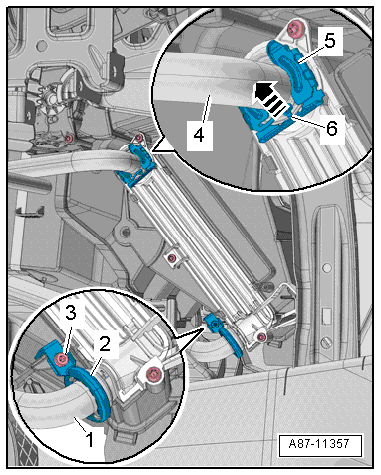
| – |
Lift locking element -6-,
remove clip -5- and pull coolant
line -4- off heat exchanger. |
| – |
Remove screw-type clip -2- and
pull coolant line -1- off heat
exchanger. |
| – |
Seal off open lines and connections with clean plugs from
engine bung set -VAS 6122-. |
|
|
|
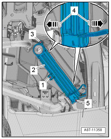
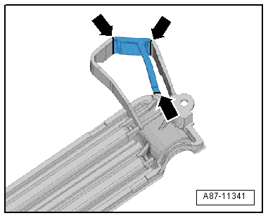
| – |
Unscrew bolts -1-,
-3- and -5-. |
| – |
Release the retainer tabs -4--arrows-
and detach the cover -2-. |
|
|
|
| – |
If noise insulation cannot be pulled out, cut open tabs on
cover -arrows-. |
| – |
Take out the heat exchanger to the left. |
| Installation is carried out in the reverse order. When
installing, note the following: |
Note
| – |
Check heater slot for dirt with heat exchanger removed. |
| – |
If necessary, remove any dirt and coolant residue. |
| – |
Vehicles with TDI engine: With auxiliary air heater element
removed, check heating element slot for dirt and clean if
necessary. |
|
|
|
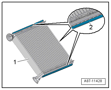
| – |
Check the foam seals -2-
attached to the heat exchanger -1-
for damage and replace if necessary. |
Note
| If the foam seal is not bonded in, it may roll up when the
heat exchanger is fitted. |
| Cold air may flow past the heat exchanger if the foam seal
is damaged or not properly fitted. |
|
|
|
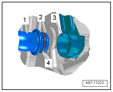
| – |
Check connection -3- of the
heat exchanger and connection -2-
of the coolant pipes for damage or contamination. |
| – |
Clean and smoothen sealing surface for seals. |
| – |
Moisten new seals -4- with
coolant (or lubricate lightly with silicone grease) and fit them
to coolant pipe -1-. |
| – |
Carefully slide heat exchanger into heater and air
conditioning unit as far as stop. |
Note
| When sliding in the heat exchanger, make sure not to damage
the connections and coolant pipes. |
| – |
Push coolant pipes into heat exchanger as far as stop. |
Risk of malfunction on heat exchanger due to defective seals and
leaks.Never squeeze seals.Never cant coolant pipes.Slide on coolant
pipes completely. |
|
|
| – |
Fit new clip -5- or screw-type
clip -2- onto joint of coolant pipe
and heat exchanger. |
| – |
Tighten bolt -3-
→ Chapter „Assembly overview - heater and air conditioning unit“. |
| – |
Check clip and screw-type clip for proper seating on
connections of heat exchanger and check coolant pipes. The
coolant pipes must not contact air distribution housing or any
other components. |
| – |
Fill with coolant
→ Rep. gr.19. |
| – |
Read event memory, and clear any entries displayed vehicle
diagnostic tester in “Guided fault finding” mode. |
| – |
As a final step, check operation of heater and air
conditioner. |
| → Chapter „Assembly overview - heater and air conditioning unit“ |
| Turbocharger; Assembly overview - turbocharger
→ Rep. gr.21. |
| Centre console; Assembly overview - centre console
→ General body repairs, interior; Rep. gr.68 |
| Knee airbags; Assembly overview - knee airbag
→ General body repairs, interior; Rep. gr.69. |
|
|
|
Removing
–
Remove centre console
→ General body repairs, interior; Rep. gr.68.
–
R ...
Special tools and workshop equipment
required
Drip tray for workshop hoist -VAS 6208-
& ...
© 2016-2026 Copyright www.vwgolf.org

 Removing and installing auxiliary air heater element - Z35- with auxiliary
air heater control unit - J604-, RHD vehicles
Removing and installing auxiliary air heater element - Z35- with auxiliary
air heater control unit - J604-, RHD vehicles Removing and installing Valeo heat exchanger, RHD vehicles