Volkswagen Golf Service & Repair Manual: Removing and installing steering column electronics control unit -J527-,
Kostal
 Note
Note
| Airbag coil connector and return ring with slip ring -F138-
is integrated in steering column electronics control unit
-J527-. |
| When renewing the control unit, select “Renew” function for
the respective control unit in “Guided fault finding” or “Guided
functions” mode → Vehicle
diagnostic tester. |
| – |
Turn wheels to straight-ahead position – steering wheel in
straight-ahead position. |
| – |
Move steering wheel to rearmost and lowest position. Use the
entire range of adjustment of the steering column for this
purpose. |
| – |
Remove steering wheel
→ Running gear, axles, steering; Rep. gr.48. |
| – |
Remove lower steering column trim
→ General body repairs, interior; Rep. gr.68. |
 WARNING
| Risk of damage to the electronic components due to
electrostatic discharge. |
| Before disconnecting the electrical connector, the
mechanics must electrostatically discharge themselves by
briefly grasping hold of door striker plate or similar. |
|
|
|
|
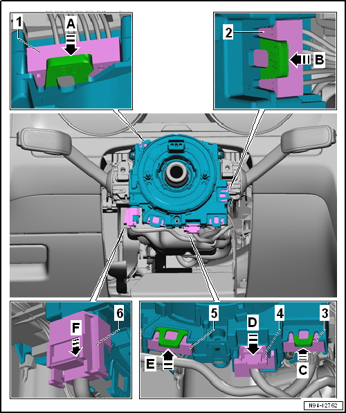
| – |
Press connector lock in direction of arrow -A-
and disconnect electrical connector -1-. |
| – |
Press connector lock in direction of arrow -B-
and disconnect electrical connector -2-. |
| – |
Press connector lock in direction of arrow -C-
and disconnect electrical connector -3-. |
| – |
Pull out connector lock in direction of arrow
-D- and press it down. |
| – |
Disconnect electrical connector -4-. |
| – |
Press connector lock in direction of arrow -E-
and disconnect electrical connector -5-. |
| – |
Pull out connector lock in direction of arrow
-F- and press it down. |
| – |
Disconnect electrical connector -6-. |
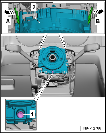
| – |
Release retaining tabs in direction of arrows
-A- and -B-. |
| – |
Remove steering column electronics control unit -J527--2-
from steering column combination switch -E595-. |
| Install in the reverse order of removal, observing the
following: |
|
|
|
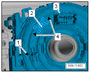
| – |
Before pushing on steering column electronics control unit
-J527--3-, ensure the following: |
| The “arrows”-1- must align. |
| Coil connector -2- must be
visible through window between “arrows”-4-. |
| – |
All connectors must be engaged securely. |
| → Chapter „Assembly overview - steering column switch module“ |
|
|
|
Removing
–
Move steering wheel to rearmost and lowest position. Use the
entire range of adjustment of the steering column for this
...
Note
Airbag coil connector and return ring with slip ring -F138-
is integrated in steering column electronics control unit
-J527-.
...
Other materials:
Changing bulbs in xenon headlights
Fig. 235 In the engine compartment: ① cover
in left-hand xenon headlight, ② cornering light, ③ turn signal, ④ side light and
daytime running light
First read and observe the introductory information
and safety warningsThe front headlight does not need to be removed when changing
bu ...
Assembly overview - brake caliper (PC57 brakes)
When carrying out repairs, install all parts supplied in repair kit.
Use only methylated spirits for cleaning the brake.
Apply thin coat of assembly paste G 052 150 A2 to brake cylinder,
piston and sealing ring.
1 -& ...
Description and function of the airbags
First read and observe the introductory information
and safety warnings The airbags can protect vehicle occupants during frontal
and side collisions by reducing their movement in the direction of the collision.
When an airbag is triggered, it is inflated by a gas generator. This causes the ...
© 2016-2026 Copyright www.vwgolf.org

 Removing and installing steering column switch module, Valeo
 Removing and installing steering column electronics control unit -J527-,
Valeo
Removing and installing steering column electronics control unit -J527-,
Valeo