Volkswagen Golf Service & Repair Manual: Removing and installing rear interior light/reading light
 Caution
| Danger of damage to component surfaces. |
| When using leverage tools, mask visible areas of the
component with commercially available adhesive tape. |
|
 Note Note
| The buttons are an integral part of the rear interior light
-WX2- and cannot be removed individually. |
| The rear interior light -WX2- is secured by a two-stage
locking mechanism. |
|
|
|
| – |
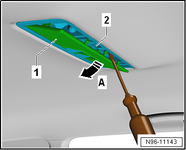
Lever out lens -1- in direction
of arrow -A- using, for example, a
narrow screwdriver. |
| – |
Remove lens -1- from rear
interior light -WX2--2-. |
|
|
|
| – |
Release catches -2- in
direction of arrow -A- using, for
example, a narrow screwdriver. |
| – |
Press locking mechanism -1- in
direction of arrow -C-. |
|
|

|
| – |
Remove rear interior light -WX2--1-
from roof aperture in direction of arrow
-A-. |
| – |
Press connector lock in direction of arrow
-B- and disconnect electrical
connector -C-. |
| Install in the reverse order of removal, observing the
following: |
Note
| Electrical connector must face direction of travel. |
|
|

|
| – |
Press locking mechanism -1- in
direction of arrow -C-. Catches
-2- must engage audibly. |
|
|
|
Special tools and workshop equipment
required
Removal wedge -3409-
Note
...
Note
The front right reading light button -E634- is an integral
part of the front interior light -WX1- and cannot be removed
individually.
...
Other materials:
Assembly overview - wheel housing trim, estate
Note
The illustration shows the wheel housing trim on the left side.
The right-hand side is similar (mirror image of left-hand side).
I: Vehicles without side padding
II: Vehicles with side padding
1 -
Wheel housing tri ...
Assembly overview - three-point seat belt, 4-door model, with belt tensioner
1 -
Belt inertia reel
Removing and installing
→ Chapter
2 -
Electrical wiring harness
3 -
Bolt
If removed due to an accident with seat belt fastened, renew bolt
40 Nm
4 ...
Replacing the battery
Fig. 25 Vehicle key: opening the battery
case cover
Fig. 26 Vehicle key: removing the battery
First read and observe the introductory information
and safety warnings Volkswagen recommends having the battery changed by a
qualified workshop.
The battery is located on the rear side of the ...
© 2016-2026 Copyright www.vwgolf.org

 Removing and installing front interior light/reading light
 Removing and installing front right reading light button -E634-