Volkswagen Golf Service & Repair Manual: Removing and installing fresh air/recirculated air, air flow flap control
motor -V425-, RHD vehicles
| Special tools and workshop equipment
required |
| Vehicle diagnostic tester |
 Note Note
| The control motor has end stops with integrated limit
switches instead of a potentiometer. |
| First carry out the following work: |
| – |
Switch off all electrical consumers. |
| – |
Remove dash panel central tube
→ General body repairs, interior; Rep. gr.70. |
|
|
|
| – |
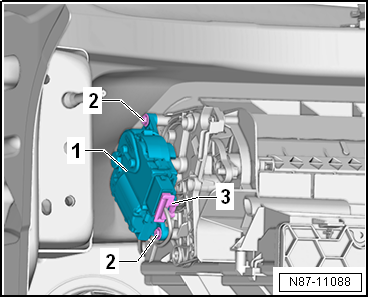
Remove fresh air/recirculated air, air flow flap control
motor -V425--1- from air intake
duct. |
| – |
Disconnect electrical connector -3-. |
|
|
|
| Installation is carried out in the reverse order. When
installing, note the following: |
Note
| Check operation of flaps and hinge mechanism before fitting. |
| Make sure levers and shafts are properly fitted in the
mounts. |
| – |
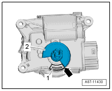
Fresh air flap must be set to “open” position, in order to
allow fresh air to flow into the vehicle. |
| The operating shaft -2- must be
on the stop -1--arrow- as shown. |
Note
| If the control motor operating shaft is not on the “fresh
air mode” stop, rotate the receptacle in the control motor. |
| – |
Switch on ignition, connect respective control motor to
vehicle wiring harness and select a setting on operating and
display unit to set control motor to desired position (e.g.
mid-position). Wait until control motor has moved to desired
position and switch off ignition. |
| – |
Position the control motor on the air intake box. The
operating shaft must engage in the receptacle. |
| There must not be any play in the connection between the
operating shaft and receptacle. |
Note
| If the bolts cannot be fitted, the control motor is not
completely seated on the housing. |
| – |
Route wiring harness so that it cannot come into contact
with any moving parts (e.g. actuating arm on control motor). |
| – |
Read event memory, and clear any entries displayed. Then,
perform “basic setting”vehicle diagnostic tester in “Guided
fault finding” mode. |
| – |
As a final step, check operation of heater and air
conditioning system. |
| → Chapter „Assembly overview - heater and air conditioning unit“ |
| Assembly overview - dash panel central tube
→ General body repairs, interior; Rep. gr.70. |
| Assembly overview - dash panel
→ General body repairs, interior; Rep. gr.70. |
|
|
|
Special tools and workshop equipment
required
Vehicle diagnostic tester
First carry out the following work:
...
Special tools and workshop equipment
required
Vehicle diagnostic tester
First carry out the following work:
...
Other materials:
Introduction
This chapter contains information on the following subjects:
→ An economic driving style
→ Driving in a fuel-efficient manner
Fuel consumption, environmental impact and wear on the engine, brakes and tyres
depend largely on three factors:
Personal driving style.
...
Removing and installing window regulator motor -V26-/-V27
Special tools and workshop equipment
required
Note
Removal and installation are only described for the
left window regulator motor. ...
Hitching and connecting the trailer
First read and observe the introductory information
and safety warnings Emergency breakaway cable
Always fasten the trailer's emergency breakaway cable properly to the towing
vehicle. Leave enough slack in the emergency breakaway cable so that the vehicle
can still drive around corners ...
© 2016-2026 Copyright www.vwgolf.org

 Removing and installing fresh air/recirculated air, air flow flap control
motor -V425-, LHD vehicles
Removing and installing fresh air/recirculated air, air flow flap control
motor -V425-, LHD vehicles Removing and installing front air distribution flap control motor -V426-,
LHD vehicles
Removing and installing front air distribution flap control motor -V426-,
LHD vehicles