Volkswagen Golf Service & Repair Manual: Removing and installing cylinder head
| Special tools and workshop equipment
required |
|
|
|
 Note Note
| Fit all heat shield sleeves in the same place when
installing. |
| – |
Remove camshaft housing
→ Chapter. |
| – |
Remove intake manifold
→ Chapter. |
|
|
|
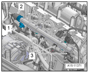
| – |
Separate electrical connectors: |
| 1 - |
On oil pressure switch for reduced oil pressure -F378- |
| 2 - |
On fuel pressure sender -G247- |
|
|
|
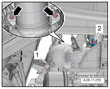
| – |
Unscrew bolt -2- and remove
screw-type clip. |
| – |
Remove bolt -1- and nuts
-arrows- and tie up catalytic
converter. |
|
|
|
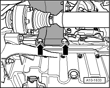
| – |
Unscrew bolts -arrows- and
remove heat shield for right drive shaft. |
|
|
|
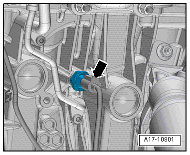
| – |
Remove heat-shield sleeve. |
| – |
Disconnect electrical connector
-arrow- on oil pressure switch -F1-. |
|
|
|
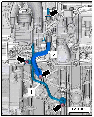
| – |
Unscrew bolts -arrows- and
detach oil supply pipe -1- and oil
return pipe -2-. |
|
|
|
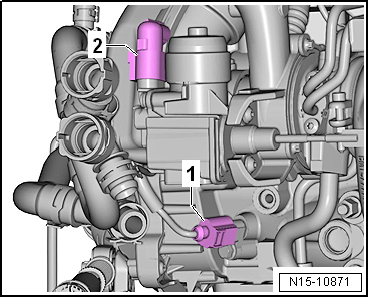
| – |
Separate electrical connectors: |
| 1 - |
For coolant temperature sender -G62- |
| 2 - |
For charge pressure positioner -V465- |
|
|
|
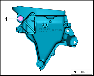
| – |
Unscrew bolt -1- from engine
support. |
|
|
|
| – |
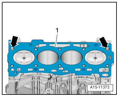
Fit cylinder head gasket -1-. |
| Note centring pins in cylinder block
-arrows-. |
| Check installation position of cylinder head gasket.
Characteristic: the part number should be legible from the inlet
side. |
| – |
If crankshaft is turned in the meantime, position piston of
No. 1 cylinder at TDC and turn crankshaft back slightly. |
| – |
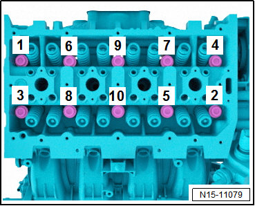
Insert cylinder head bolts and hand-tighten. |
| – |
Tighten bolts for cylinder head
→ Fig.. |
Note
| After repair work it is not necessary to retighten the
cylinder head bolts. |
| Further installation steps are carried out in the reverse
order; note the following: |
| – |
Install camshaft housing
→ Chapter. |
| – |
Install intake manifold
→ Chapter. |
| – |
Change engine oil
→ Booklet. |
| – |
Replenish coolant
→ Chapter. |
| → Fig. „“Engine support - specified torque and installation
sequence”“ |
| → Chapter „Assembly overview - cylinder head“ |
| → Chapter „Assembly overview - turbocharger“ |
| → Fig. „“Installing catalytic converter - tightening torque and
sequence”“ |
| → Running gear, axels, steering; Rep. gr.40 |
|
|
|
1 -
Bolt
Specified torque and tightening sequence
→ Fig.
2 -
Inlet camshaft control valve 1 -N205-
...
Removing
–
Remove coolant pump
→ Chapter.
–
Remove air filter housing
→&nbs ...
© 2016-2026 Copyright www.vwgolf.org

 Assembly overview - camshaft housing, engine codes CHPA, CMBA, CPVA, CXSA,
CZCA, CPVB, CZDA
Assembly overview - camshaft housing, engine codes CHPA, CMBA, CPVA, CXSA,
CZCA, CPVB, CZDA Removing and installing camshaft housing