Volkswagen Golf Service & Repair Manual: Removing and installing camshaft housing
| – |
Remove coolant pump
→ Chapter. |
| – |
Remove air filter housing
→ Chapter. |
| – |
Remove ignition coils
→ Chapter. |
| – |
Detach toothed belt from camshafts
→ Chapter. |
| – |
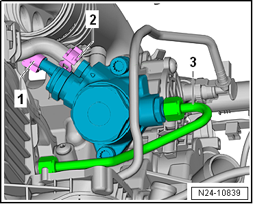
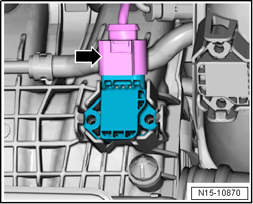
Disconnect electrical connector -1-. |
|
|
|
| – |
Detach hose clip -2- and pull
off hose. |
| – |
Remove high-pressure pipe -3-
→ Chapter. |
| – |
Disconnect electrical connector -2-. |
|
|
|
| – |
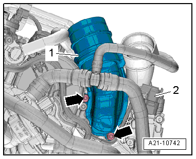
Remove bolts -arrows- and
detach connection -1-. |
|
|
|
| – |
Release hose clip -2- and
detach coolant hose. |
| – |
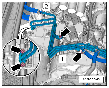
Remove bolts -arrows- and pivot
coolant lines -1- to right side. |
|
|
|
| – |
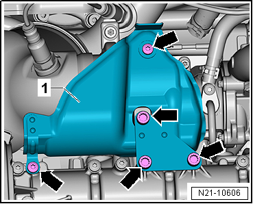
Unscrew bolts -arrows- and
remove heat shield -1-. |
|
|
|
| – |
Disconnect connector -arrow-
from intake manifold sender -GX9-. |
|
|
|
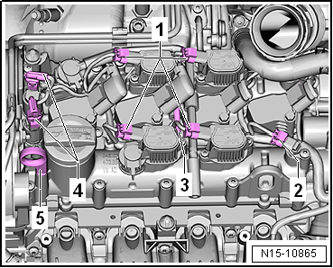
| – |
Separate electrical connectors: |
| 1 - |
For cam actuators -N583-/-N587-/-N591-/-N595- (only for CPTA) |
| 2 - |
For Hall sender -G40- and Hall sender 3 -G300- (only for
CPTA, CHPA) |
| 4 - |
For camshaft control valve 1 -N205- and exhaust camshaft
control valve 1 -N318- (only for CPTA, CHPA) |
| – |
Unscrew bolt -3- and lay wiring
harness clear to one side. |
|
|
|
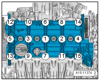
| – |
Loosen bolts for camshaft housing in the sequence
-15 ... 1- and remove. |
| – |
Carefully detach camshaft housing from adhesive bond and
remove it. |
| – |
Mark allocation of roller rocker fingers and compensation
elements for reinstallation. |
| – |
Remove roller rocker fingers together with compensation
elements and place them on a clean surface. |
 Note Note
| Renew bolts that are tightened with specified tightening
angle. |
| Renew gasket and seal with oil strainer. |
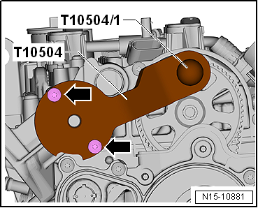
| – |
Check “TDC” position of camshaft and crankshaft: |
|
|
|
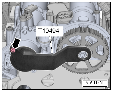
| Camshaft clamp -T10504- fitted on camshaft housing. |
| Engine codes CHPA, CMBA, CPVA, CXSA, CZDA, CZCA, CPVB |
|
|
|
| Camshaft clamp -T10494- must be attached to camshaft
housing. |
Risk of damage to valve gear caused by camshafts being moved in axial
direction.Never move camshafts in axial direction when turning them.
|
|
|
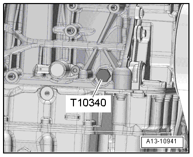
| Locking pin -T10340- screwed into cylinder block as far as
stop and tightened to 30 Nm. |
| Crankshaft has been turned in direction of engine rotation
until it rests against locking pin -T10340- = “TDC” position. |
|
|
|
| – |
Check, if all roller rocker fingers are seated properly on
valve stem end and if they are clipped into the respective
compensation element. |
Note
| The oil strainer is fitted only if the cylinder head has the
appropriate recess. |
| Cylinder heads with recess do not require an oil strainer. |
| – |
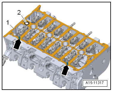
Fit seal with oil strainer -2-
into cylinder head -1-. |
| – |
Fit gasket onto dowel pins -arrows-. |
|
|
|
| – |
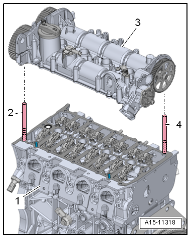
Screw 2 studs -items 2, 4-
(e.g. -T10288/4-) into cylinder head. |
| – |
Carefully lower camshaft housing -3-
vertically onto studs in cylinder head. |
Note
| Ensure that camshaft housing is not canted. |
| – |
Tighten bolts for camshaft housing. |
| Specified torque and tightening sequence, engine codes CPTA,
CZEA
→ Fig.. |
| Specified torque and tightening sequence, engine codes CHPA,
CMBA, CPVA, CXSA, CZDA, CZCA, CPVB
→ Fig. |
| Remaining installation steps are carried out in reverse
sequence; note the following: |
| – |
Install high-pressure pipe
→ Chapter. |
| – |
Install toothed belt (adjust valve timing)
→ Chapter. |
| – |
Install ignition coils
→ Chapter. |
| – |
Install coolant pump
→ Chapter. |
| – |
Electrical connections and routing → Current
flow diagrams, Electrical fault finding and Fitting locations. |
| Avoid damage to valves and piston crowns after working on
valve gear. |
| Turn the engine carefully at least 2 rotations to ensure
that none of the valves make contact when the starter is
operated. |
| → Chapter „Assembly overview - camshaft housing“ |
| → Chapter „Assembly overview - turbocharger“ |
| → Chapter „Assembly overview - air filter housing“ |
|
|
|
Special tools and workshop equipment
required
Socket -3410-
Removing
...
Special tools and workshop equipment
required
Spark plug socket and extension -3122 B-
...
Other materials:
Interior monitoring system and anti-tow alarm
Fig. 32 Next to the driver seat: button
for switching off the interior monitoring system and anti-tow alarm
Fig. 33 In the roof console: sensors for
the interior monitoring system
First read and observe the introductory information
and safety warnings The interior monitoring system will ...
Belt height adjuster
Fig. 68 Next to the front seats: belt height
adjuster
First read and observe the introductory information
and safety warnings The seat belt height adjusters for the front seats can
be used to adjust the position of the seat belt on the shoulder so that it can be
fastened properly:
P ...
Swellings in the tyre sidewall
A swelling in the sidewall of the tyre indicates that the
substructure of the carcass has been damaged.
Typical causes for such damage include, for example, driving
over kerbs at a sharp angle.
...
© 2016-2026 Copyright www.vwgolf.org

 Removing and installing cylinder head
 Checking compression