Volkswagen Golf Service & Repair Manual: Removing and installing control unit for electronic steering column lock
-J764-
 Note Note
| When renewing control unit, select
Renewal function for respective control unit in “Guided
fault finding” or “Guided functions” using → Vehicle
diagnostic tester. |
| Special tools and workshop equipment
required |
|
|
|
| – |
Remove steering column switch module
→ Electrical system; Rep. gr.94. |
|
|
|
| – |
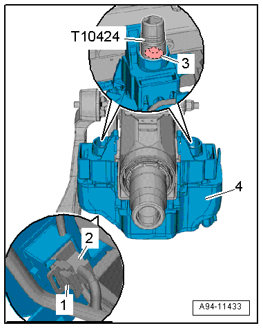
Disconnect connector -2-. To do
this, slide catch -1- to rear and
push release downwards. |
| – |
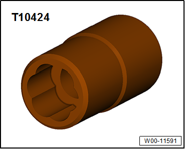
Unscrew shear-head bolt -3-
using socket -T10424-. |
| – |
Remove control unit for electronic steering column lock
-J764--item 4- |
Note
| If the shear-head bolt cannot be removed using socket
-T10424-, drill out using an angle drill and an 8.5 mm twist
drill. |
| Install in reverse order of removal, observing the
following: |
|
|
|
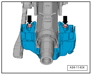
| – |
Tighten new bolts -arrow- until
shear-head shears off. |
|
|
|
Special tools and workshop equipment
required
Torque wrench -V.A.G 1331-
...
© 2016-2026 Copyright www.vwgolf.org

 Removing and installing steering column, RHD
 Steering rack