Volkswagen Golf Service & Repair Manual: Principle circuit diagrams for various purging circuits
 Note Note
| The arrows in the following illustrations show the direction
of flow of the refrigerant during purging. The refrigerant flows
against the direction of flow during normal conditioning of the
air, which is why the high-pressure system of the air
conditioner service station is connected to the low-pressure
connection of the refrigerant circuit to the air conditioner
compressor. |
| These principle circuit diagrams show a refrigerant circuit
with restrictor and reservoir and a refrigerant circuit with
expansion valve, receiver and a second evaporator (extra
equipment on certain vehicles). |
| Depending on the design of the air conditioner service
station, non-return valves may be installed between the
refrigerant circuit and the air conditioner service station.
This ensures the correct direction of flow of refrigerant during
purging. |
| Refrigerant circuit with restrictor and reservoir |
Note
| On vehicles with restrictor and reservoir, the restrictor
and the reservoir are removed. The refrigerant pipes of the
restrictor are assembled again. The refrigerant pipes to the
removed reservoir are joined together with two adapters and the
charging hose -VAS 6338/31- (from adapter case VW/Audi passenger
vehicle set -VAS 6338/1-. |
|
|
|
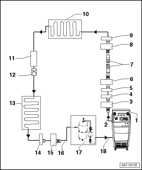
| 1 - |
Air conditioner service station |
| With electronics and a purging programme e.g. air conditioner
service station -VAS 6380- with purging device or air conditioner
service station with purging device -VAS 6337-. |
| If an air conditioner service station without purging programme is
used, the sequence has to be carried out manually (evacuate, purge
3 times with at least 4 kg of refrigerant each time and extract
refrigerant again, evacuate). |
| 2 - |
Refrigerant hose of air conditioner service station |
| From high pressure side of air conditioner service station (normally
coloured red) to connection for low pressure side of air conditioner
compressor on refrigerant circuit (larger diameter) |
| 3 - |
Adapter to connection for low-pressure side on refrigerant circuit |
| Different versions depending on vehicle
→ Chapter. |
| From adapter case VW/Audi passenger vehicle set -VAS 6338/1-. |
| 4 - |
Connection for low-pressure side on refrigerant circuit |
| Different versions depending on vehicle
→ Chapter. |
| On refrigerant line from air conditioner compressor to reservoir |
| 5 - |
Connection to reservoir |
| Different versions depending on vehicle
→ Chapter. |
| On refrigerant line from air conditioner compressor to reservoir |
| 6 - |
Adapter to bridge removed reservoir |
| Different versions depending on vehicle
→ Chapter. |
| From adapter case VW/Audi passenger vehicle set -VAS 6338/1-. |
| 7 - |
Charging hose for refrigerant
→ Chapter |
| For example charging hose -VAS 6338/31- (from adapter case VW/Audi
passenger vehicle set -VAS 6338/1-). |
| 8 - |
Adapter to bridge removed reservoir |
| Different versions depending on vehicle
→ Chapter. |
| From adapter case VW/Audi passenger vehicle set -VAS 6338/1-. |
| 9 - |
Connection to reservoir |
| Different versions depending on vehicle
→ Chapter. |
| 11 - |
Location of restrictor |
| The restrictor is removed. |
| Removing restrictor
→ Heating, air conditioning. |
| 12 - |
Threaded connection in refrigerant line |
| After removing the restrictor, screw back together again
→ Heating, air conditioning. |
| 14 - |
Connection for high-pressure side on refrigerant circuit |
| Different versions depending on vehicle
→ Chapter. |
| 15 - |
Adapter to connection for high-pressure side on refrigerant circuit |
| Different versions depending on vehicle
→ Chapter. |
| From adapter case VW/Audi passenger vehicle set -VAS 6338/1-. |
| 16 - |
Charging hose of flushing device for refrigerant circuits |
| From connection to high-pressure side of air conditioner compressor
on refrigerant circuit (smaller diameter) to inlet of purging device for
refrigerant circuits -VAS 6336/1- or purging device for refrigerant
circuits -VAS 6337/1-. |
| 17 - |
Purging device for refrigerant circuits |
| Different versions and different design e.g. purging device for
refrigerant circuits -VAS 6336/1- or purging device for refrigerant
circuits -VAS 6337/1-. |
| With filter, sight glass, safety valve, heating, refrigerant tank,
etc. (depending on version). |
| Depending on the design of the air conditioner service station and
the purging device for refrigerant circuits, there may be a non-return
valve installed at the outlet of the purging device for refrigerant
circuits (to assure the correct direction of refrigerant flow during
purging). |
| 18 - |
Refrigerant hose of air conditioner service station |
| From the low-pressure side of the air conditioner service station
(normally coloured blue) to the outlet of the purging device for
refrigerant circuits |
| Refrigerant circuit with expansion valve, receiver and
second evaporator |
Note
| This principle circuit diagram shows a refrigerant circuit
with expansion valve, receiver and a second evaporator (extra
equipment on certain vehicles). |
| On vehicles with expansion valve and receiver, the expansion
valve is removed and an adapter installed in its place. The
receiver must be purged, depending on the vehicle or the dryer
cartridge removed. Depending on the type of receiver, this
should be removed and the line connections to the receiver
joined together using two adapters and a charging hose. |
| On vehicles with just one evaporator, the components from
position “16” are not installed or not required. |
|
|
|
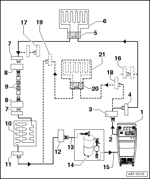
| 1 - |
Air conditioner service station |
| With electronics and a purging programme e.g. air conditioner
service station -VAS 6380- with purging device or air conditioner
service station with purging device -VAS 6337-. |
| If an air conditioner service station is used which does not have a
purging programme, then the sequence must be performed manually.
|
| – |
Extract refrigerant, if there is any in the system. |
| – |
Connect purging device for refrigerant circuits -VAS 6336/1- or
purging device for refrigerant circuits -VAS 6337/1- between air
conditioner service station and return line for refrigerant circuit. |
| – |
Evacuate refrigerant circuit for 20 minutes, then fill system with
4 kg of refrigerant R134a. Then extract again and repeat process two
further times. If after the 3rd purging process the refrigerant in the
sight glass/glasses is not clear, repeat process again. |
| 2 - |
Refrigerant hose of air conditioner service station |
| From high pressure side of air conditioner service station (normally
coloured red) to connection for low pressure side of air conditioner
compressor on refrigerant circuit (larger diameter) |
| 3 - |
Adapter to connection for low-pressure side on refrigerant circuit |
| Different versions depending on vehicle
→ Chapter. |
| From adapter case VW/Audi passenger vehicle set -VAS 6338/1-. |
| 4 - |
Connection for low-pressure side on refrigerant circuit |
| Different versions depending on vehicle
→ Chapter. |
| 5 - |
Adapter for removed expansion valve |
| Different versions depending on vehicle
→ Chapter. |
| From adapter case VW/Audi passenger vehicle set -VAS 6338/1-. |
| 7 - |
Connection to receiver |
| Different versions depending on vehicle
→ Chapter. |
| Not included on vehicles with a dryer cartridge in the receiver on
the condenser or one in the receiver integrated within the condenser
→ Heating, air conditioning. |
| 8 - |
Adapter to bridge removed receiver |
| Not required on all vehicles. |
| Different versions depending on vehicle
→ Chapter. |
| From adapter case VW/Audi passenger vehicle set -VAS 6338/1-. |
| 9 - |
Charging hose for refrigerant
→ Chapter |
| For example charging hose -VAS 6338/31- (from adapter case VW/Audi
passenger vehicle set -VAS 6338/1-). |
| If there is a receiver with dryer cartridge installed on the
condenser, the dryer cartridge must be removed (seal receiver again on
or in condenser following removal)
→ Heating, air conditioning. |
| If the receiver is attached directly to the condenser, remove the
receiver after purging and renew
→ Heating, air conditioning. |
| 11 - |
Connection for high-pressure side on refrigerant circuit |
| Different versions depending on vehicle
→ Chapter. |
| 12 - |
Adapter to connection for high-pressure side on refrigerant circuit |
| Different versions depending on vehicle
→ Chapter. |
| From adapter case VW/Audi passenger vehicle set -VAS 6338/1-. |
| 13 - |
Charging hose of flushing device for refrigerant circuits |
| From connection to high pressure side of air conditioner compressor
on refrigerant circuit (smaller diameter) to inlet of purging device for
refrigerant circuits. |
| 14 - |
Purging device for refrigerant circuits |
| Different versions and different design e.g. purging device for
refrigerant circuits -VAS 6336/1- or purging device for refrigerant
circuits -VAS 6337/1-. |
| With filter, sight glass, safety valve, heating, refrigerant tank,
etc. (depending on version). |
| Depending on the design of the air conditioner service station and
the purging device for refrigerant circuits, there may be a non-return
valve installed at the outlet of the purging device for refrigerant
circuits (to assure the correct direction of refrigerant flow during
purging). |
| 15 - |
Refrigerant hose of air conditioner service station |
| From the low-pressure side of the air conditioner service station
(normally coloured blue) to the outlet of the purging device for
refrigerant circuits |
| 16 - |
Adapter to seal outlet to second evaporator |
| Only required on certain vehicles with “second evaporator” (optional
equipment). |
| From adapter case commercial vehicle set -VAS 6338/50-. |
| 17 - |
Adapter to seal outlet to second evaporator |
| Only required on certain vehicles with “second evaporator” (optional
equipment). |
| From adapter case commercial vehicle set -VAS 6338/50-. |
| 18 - |
Connection of low-pressure side on refrigerant circuit to second
evaporator |
| Different versions depending on vehicle
→ Chapter. |
| Only fitted on certain vehicles with “second evaporator” (optional
equipment). |
| 19 - |
Connection of high-pressure side on refrigerant circuit to second
evaporator |
| Different versions depending on vehicle
→ Chapter. |
| Only fitted on certain vehicles with “second evaporator” (optional
equipment). |
| 20 - |
Adapter for removed expansion valve on second evaporator |
| Different versions depending on vehicle
→ Chapter. |
| Only required on certain vehicles with “second evaporator” (optional
equipment). |
| From adapter case commercial vehicle set -VAS 6338/50-. |
| Only fitted on certain vehicles with “second evaporator” (optional
equipment). |
Vehicles with high-voltage system (hybrid vehicles)
Observe the additional warning instructions for working on
vehicles with high-voltage system
...
Vehicles with high-voltage system
Observe the additional warning instructions for working on
vehicles with high-voltage system
→ Ele ...
Other materials:
Assembly overview - FS III front brake
Note
After every brake pad change, depress brake pedal firmly several
times with vehicle stationary, so that brake pads are properly seated in
their normal operating position.
Use the brake filling and bleeding equipment -VAS 5234- to draw off
brake ...
Wheel allocation
6 J x 15
6 J x 15
Note
Always observe the allocation of wheels and tyres to the respective
engines, which are listed in the overview table.
Explanation of information on
wheels:
→ Wheels and Tyres Guide - General informatio ...
Distribution of the refrigerant circuit components and their influence on
the high-pressure and low-pressure sides
On the high-pressure side, there are the condenser, the
receiver and the restrictor or expansion valve that acts as the
separation between the high-pressure fluid and low-pressure
fluid sides.
High pressure is created because the restric ...
© 2016-2026 Copyright www.vwgolf.org

 Purging (cleaning) refrigerant circuit with refrigerant R134a
 Purging electrical air conditioner compressor