Volkswagen Golf Service & Repair Manual: Schematic diagram - coolant hoses, Golf GTE
 Note Note
| Currently, only the auxiliary heater function is available.
At the moment the auxiliary heater is not intended to be
operated as a supplementary heater. In vehicles with a
high-voltage system, the high-voltage heater (PTC) -Z115- is
used as a supplementary heater
→ Heating, air conditioning; Rep. gr.87. |
| In vehicles with a high-voltage system, the high-voltage
heater (PTC) -Z115- can be used for heating the passenger
compartment. |
| Topping up coolant and bleeding coolant circuit
→ Rep. gr.19 and
→ Chapter |
| Incorporation of heat exchanger for air conditioning system
and auxiliary heater into coolant circuit of engine
→ Engine mechanics; Rep. gr.19 (coolant hose
schematic diagram). |
|
|
|
Note
| The -arrows- indicate the direction of
coolant flow. |
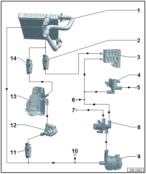
| 1 - |
Heat exchanger for heater and air conditioning unit |
| Incorporation of heat exchanger into engine coolant circuit
→ Engine mechanics; Rep. gr.19 (coolant hose schematic
diagram). |
| Installed in coolant line between high-voltage heater (PTC) -Z115-
and heat exchanger of heater and air conditioning unit. |
| Install with correct orientation and ensure proper operation |
| Removing and installing
→ Engine mechanics; Rep. gr.19 |
Note
| Prevents coolant from flowing back from the auxiliary heater (via
the high-voltage heater (PTC) -Z115-) to the engine when the auxiliary
heater is switched on (and the engine and/or the coolant pump for
high-temperature circuit -V467- are not running). |
| If there are customer complaints about poor heat output of the air
conditioning system in auxiliary heater mode, make sure the non-return
valve is installed with correct orientation and that it works properly. |
| If there are customer complaints about poor heat output of the air
conditioning system when the auxiliary heater is switched on (and the
auxiliary heater is activated for heating the coolant in place of the
-Z115-), make sure the non-return valve is installed with correct
orientation and that it works properly. |
| 3 - |
High-voltage heater (PTC) - Z115- (with high-voltage heater (PTC)
control unit - J848-) |
| Check; vehicle diagnostic tester in “Guided fault finding” mode (of
air conditioning system) and → Current flow
diagrams, Electrical fault finding and Fitting locations |
| Removing and installing
→ Heating, air conditioning; Rep. gr.87 |
| 4 - |
Coolant valve for gearbox -N488- |
| Removing and installing
→ Engine mechanics; Rep. gr.19 |
| Check; vehicle diagnostic tester in “Guided fault finding” mode (of
engine) and → Current flow
diagrams, Electrical fault finding and Fitting locations |
| 5 - |
Coolant supply to gearbox |
| Incorporation into coolant circuit of engine (and gearbox)
→ Engine mechanics; Rep. gr.19 (coolant hose schematic
diagram). |
| 6 - |
Coolant supply from engine |
| Incorporation into engine coolant circuit
→ Engine mechanics; Rep. gr.19 (coolant hose schematic
diagram). |
| 7 - |
Coolant return to the engine |
| Incorporation into engine coolant circuit
→ Engine mechanics; Rep. gr.19 (coolant hose schematic
diagram). |
| 8 - |
Coolant changeover valve 2 -N633- |
| Incorporation into engine coolant circuit
→ Engine mechanics; Rep. gr.19 (coolant hose schematic
diagram). |
| Removing and installing
→ Engine mechanics; Rep. gr.19 |
Note
| The -N633- is activated by the respective engine control unit (e.g.
by engine control unit -J623-), if heat output is required from the air
conditioning system and the “auxiliary heater” function is activated,
but the auxiliary heater itself is not activated (the -Z115- is used for
the auxiliary heater function instead) or if the vehicle is in electric
drive mode; → Current flow
diagrams, Electrical fault finding and Fitting locations and
vehicle diagnostic tester in “Guided fault finding” mode. |
| If there are customer complaints about poor heat output of the air
conditioning system when the auxiliary heater is switched off (with
engine running and/or at standstill, irrespective of whether -Z115- is
activated or not), make sure the coolant changeover valve 2 is installed
with correct orientation and that it works properly → Current flow
diagrams, Electrical fault finding and Fitting locations and
vehicle diagnostic tester in “Guided fault finding” mode. |
| To ensure that the coolant heated by the -Z115- is conveyed through
the heat exchanger of heater and air conditioning unit, the coolant pump
for high-temperature circuit -V467- and the coolant valve for gearbox
-N488- must be activated as well (by the respective engine control
unit). To ensure that the coolant flows into the correct direction, the
non-return valves installed in the coolant circuit must be installed
correctly and they must work properly. For additional information refer
to
→ Engine mechanics; Rep. gr.19 (coolant hose schematic
diagram); vehicle diagnostic tester in “Guided fault finding” mode
→ Current flow
diagrams, Electrical fault finding and Fitting locations. |
| 9 - |
Coolant pump for high-temperature circuit -V467- |
| Incorporation into engine coolant circuit
→ Engine mechanics; Rep. gr.19 (coolant hose schematic
diagram). |
| Removing and installing
→ Engine mechanics; Rep. gr.19 |
Note
| The -V467- is activated by the respective engine control unit (e.g.
by engine control unit -J623-), if heat output from the air conditioning
system is required → Current flow
diagrams, Electrical fault finding and Fitting locations and
vehicle diagnostic tester in “Guided fault finding” mode. |
| If there are customer complaints about poor heat output of the air
conditioning system when the auxiliary heater is switched off (with
engine running and/or at standstill, irrespective of whether -Z115- is
activated or not), make sure the coolant changeover valve 2 is installed
with correct orientation and that it works properly → Current flow
diagrams, Electrical fault finding and Fitting locations and
vehicle diagnostic tester in “Guided fault finding” mode. |
| To ensure that the coolant heated by the -Z115- is conveyed through
the heat exchanger of heater and air conditioning unit, the coolant
changeover valve 2 -N633- and the coolant valve for gearbox -N488- must
be activated as well (by the respective engine control unit). To ensure
that the coolant flows into the correct direction, the non-return valves
installed in the coolant circuit (
→ Item and
→ Item) must be installed correctly and they must work
properly. For additional information refer to
→ Engine mechanics; Rep. gr.19 (coolant hose schematic
diagram); vehicle diagnostic tester in “Guided fault finding” mode
→ Current flow
diagrams, Electrical fault finding and Fitting locations. |
| 10 - |
Coolant return from gearbox |
| Incorporation into coolant circuit of engine (and gearbox)
→ Engine mechanics; Rep. gr.19 (coolant hose schematic
diagram). |
| Depending on vehicle version, installed in coolant line between heat
exchanger of heater and air conditioning unit and circulation pump -V55-
(as shown in illustration), or in coolant line between auxiliary heater
and heat exchanger of heater and air conditioning unit
→ Item. |
| Install with correct orientation and ensure proper operation |
| Removing and installing
→ Engine mechanics; Rep. gr.19 |
Note
| Prevents coolant from flowing back via the auxiliary heater to the
engine when the auxiliary heater is switched off (and the engine and/or
the coolant pump for high-temperature circuit -V467- are running). |
| If there are customer complaints about poor heat output of the air
conditioning system when the auxiliary heater is switched off (with
engine running and/or at standstill, irrespective of whether -Z115- and
the coolant pump for high-temperature circuit -V467- are activated or
not), make sure the coolant pump/thermostat is installed with correct
orientation and that it works properly. |
| If there are customer complaints about poor heat output of the air
conditioning system when the auxiliary heater is switched on (and the
-Z115- is activated for heating the coolant in place of the auxiliary
heater), make sure the coolant pump/thermostat is installed with correct
orientation and that it works properly. |
| 12 - |
Circulation pump -V55- |
| The -V55- is integrated into the auxiliary heater's hose assembly. |
| Removing and installing
→ Chapter |
Note
| In electric drive mode (engine not running) the circulation pump
-V55- of the auxiliary heater can be activated by the auxiliary heater
control unit -J364-. The auxiliary heater control unit -J364- is
requested to switch on the circulation pump -V55- via the data bus by
the air conditioner operating unit (Climatronic control unit -J255-);
vehicle diagnostic tester in “Guided fault finding” mode. |
| Removing and installing
→ Chapter |
Note
| If the -J255- in vehicles with high-voltage system has decided that
the auxiliary heater function is required to achieve the desired
passenger compartment temperature, the auxiliary heater or the
high-voltage heater (PTC) -Z115- are activated depending on various
conditions. |
| Alternative fitting location, if not installed at
→ Item |
| For additional notes refer to
→ Item |
Note
| Installed only if the non-return valve
→ Item is not fitted |
Note
The schematic diagram for the entire coolant circuit can be
found in the repair group 19
→ Rep. gr.19.
...
The removal and installation procedures for the auxiliary
heater and the circulation pump -V55- described in this Workshop
Manual ensure that only a small quantity of ...
© 2016-2026 Copyright www.vwgolf.org

 Schematic diagram - coolant hoses, Golf and Golf Estate
 Bleeding coolant circuit of auxiliary heater