VW Golf manuals

Volkswagen Golf Service & Repair Manual: Removing and installing air recirculation flap control motor -V113-, LHD vehicles

Volkswagen Golf Service & Repair Manual / Heating, air conditioning / Air conditioner / Control motors / Removing and installing air recirculation flap control motor -V113-, LHD vehicles

Heater and air conditioning system with electric/manual controls
Special tools and workshop equipment required
Vehicle diagnostic tester
  Note
The control motor has end stops with integrated limit switches instead of a potentiometer.
First carry out the following work:
–  Switch off all electrical consumers.
–  Switch off ignition.
–  Remove ignition key.
Removing
–  Remove glove compartment → General body repairs, interior; Rep. gr.68.
   
–  Unscrew bolts -arrows-.
–  Remove air recirculation flap control motor -V113--3- from air intake duct -2-.
–  Disconnect electrical connector -1-.
Installing
 

Removing and installing air recirculation flap control motor -V113-, LHD vehicles

Installation is carried out in the reverse order. When installing, note the following:
  Note
Check operation of flaps and hinge mechanism before fitting.
Make sure levers and shafts are properly fitted in the mounts.
–  Fresh air flap must be set to “open” position, in order to allow fresh air to flow into the vehicle.
The operating shaft -2- must be on the stop -1--arrow- as shown.
  Note
If the control motor operating shaft is not on the “fresh air mode” stop, rotate the receptacle in the control motor.
–  Switch on ignition, connect respective control motor to vehicle wiring harness and select a setting on operating and display unit to set control motor to desired position (e.g. mid-position). Wait until control motor has moved to desired position and switch off ignition.
–  Position the control motor at the air intake box. The operating shaft must engage in the mount.
There must not be any play in the connection between the operating shaft and mount.
  Note
If the bolts cannot be fitted, the control motor is not completely seated on the housing.
–  Route wiring harness so that it cannot come into contact with any moving parts (e.g. actuating arm on control motor).
–  Read event memory, and clear any entries displayed. Then, perform “basic setting”vehicle diagnostic tester in “Guided fault finding” mode.
–  As a final step, check operation of heater and air conditioning system.
Specified torque
→ Chapter „Assembly overview - heater and air conditioning unit“
Compartments/covers; Assembly overview - glove compartment → General body repairs, interior; Rep. gr.68.
 

Removing and installing air recirculation flap control motor -V113-, LHD vehicles

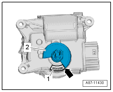
Removing and installing defroster flap control motor -V107- with potentiometer -G135-, RHD vehicles
Special tools and workshop equipment required Vehicle diagnostic tester First carry out the following work: ...

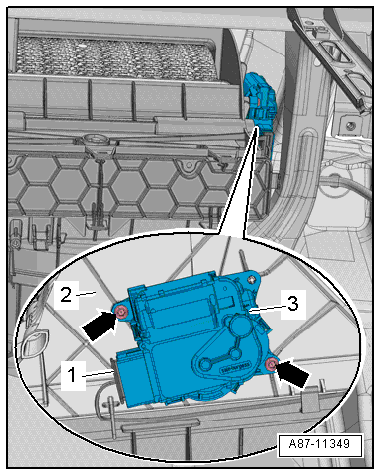
Removing and installing air recirculation flap control motor -V113-, RHD vehicles
Heater and air conditioning system with electric/manual controls Special tools and workshop equipment required Veh ...

Other materials:

Assembly overview - sun visors
  Note The assembly overview is shown for the driver side. The assembly overview for the front passenger side is analogous. 1 -  Sun visor Removing and installing → Chapter 2 -  Sun visor mount ...

Assembly overview - speed sensor on rear axle
1 -  ABS speed sensor Before inserting sensor, clean inner surface of fitting hole and coat it with high-temperature paste -G 052 112 A3-. Removing and installing → Chapter 2 -  Bolt ...

Removing and installing bracket for onboard supply control unit -J519-, RHD vehicles
Removing –  With ignition switched off, disconnect earth cable from battery → Chapter. –  Remove dash panel → General body repairs, interior; Rep. gr.70. ...

© 2016-2024 Copyright www.vwgolf.org