Volkswagen Golf Service & Repair Manual: Purging electrical air conditioner compressor
| Vehicles with high-voltage system |
| Observe the additional warning instructions for working on
vehicles with high-voltage system
→ Electrical system; Rep. gr.93. |
 WARNING
| Risk of injury due to unexpected engine start |
| When working on a high-voltage vehicle, switch off
the ignition, and deposit the ignition key somewhere
outside the passenger compartment. |
|
WARNING
| Handling high-voltage cables: |
| l |
Do not support yourself or your tools on
high-voltage cables and their components --> risk of
damage to the insulation. |
| l |
High-voltage cables must not be extensively bent or
kinked --> risk of damage to the insulation. |
| l |
The round high-voltage connectors are colour-coded
with a coloured ring on the outside and mechanically
coded with respective guide lugs. Always observe the
coding when connecting the round high-voltage connectors
in order to prevent any mechanical damage to the
high-voltage connectors.
|
|
DANGER!
| Hazardous voltage resulting from damaged
high-voltage components |
| Observe the following when working in the vicinity
of high-voltage components and cables: |
| Work involving metal-removing, deforming and
sharp-edged tools or heat sources such as welding,
soldering, hot air and thermal bonding is not permitted. |
| Before starting work, carry out a visual check on
the high-voltage components in the area of work. |
| When working in the engine compartment, carry out a
visual check on the power and control electronics for
electric drive -JX1-, the electric drive motor -V141-,
the air conditioner compressor -V470- and the
high-voltage cables.
|
| When working on the underbody, carry out a visual
check on the high-voltage cables and covers. |
| When working on the rear end, carry out a visual
check on the high-voltage cables and the maintenance
connector for high-voltage system - TW -.
|
| Carry out a visual check on all potential
equalisation lines. |
| When carrying out the visual check, observe the
following: |
| The high-voltage components must not reveal any
external damage.
|
| The insulation of the high-voltage cables and the
potential equalisation lines must not be damaged. |
| The high-voltage cables must not show any unusual
deformations.
|
| Each high-voltage component must be clearly
identified with a red warning sticker. |
|
| If repair work in the vicinity of high-voltage components
and cables is necessary, “carry out a visual check for damage on
high-voltage components and cables”, and “observe the general
warning instructions for work on the high-voltage system”
→ Electrical system; Rep. gr.93. |
| If repair work on high-voltage components is necessary, de-energise
the high-voltage system
→ Electrical system; Rep. gr.93, and “observe the
general warning instructions for work on the high-voltage
system”
→ Electrical system; Rep. gr.93. |
 Note Note
| The electrical air conditioner compressor must be purged, if
you suspect that there is too much refrigerant oil in the
refrigerant circuit or if contaminated refrigerant oil
(contaminated with moisture) must be extracted from the air
conditioner compressor. In these cases the refrigerant circuit
must be purged as well in order to clean the refrigerant circuit
and to re-establish the correct amount of refrigerant oil. |
| If an electrical air conditioner compressor is renewed
without having a mechanical fault (e.g. defective printed
circuit board), the amount of refrigerant oil from this
electrical air conditioner compressor must be determined. |
Note
| The air conditioner compressor must be purged in order to
extract the refrigerant oil which needs to be determined. |
| Purge the air conditioner compressor in normal direction of
flow (from low-pressure inlet to high-pressure outlet). |
| In order to purge as much refrigerant oil from the air
conditioner compressor as possible make sure that the
high-pressure outlet of the air conditioner compressor is in the
lowest position possible. |
| If an air conditioner service station without purging
programme is used, the sequence has to be carried out manually
(evacuate, purge 3 times with at least 2 kg of refrigerant each
time and extract refrigerant again, evacuate). |
| Determined amount e.g. 50 cmі |
| Then, remove as much refrigerant oil from the new air
conditioner compressor as is necessary to ensure that only the
same amount of refrigerant oil which has been purged from the
old air conditioner compressor remains in the new one (plus
10 cm 3). If, for example, the new
original air conditioner compressor is filled with e.g. 200 cm3
of refrigerant oil, then remove only 140 cm3. |
| – |
Pour old refrigerant oil out of air conditioner compressor.
Handling refrigerant
→ Volkswagen ServiceNet; Service handbook; Environmental
protection; Waste disposal; Current situation; Disposal
channels; Disposal of used oils; Refrigerant oils. |
Note
| If the amount of refrigerant oil which can be removed from
the new air conditioner compressor is not sufficient, the new
air conditioner compressor must be purged. After the new air
conditioner compressor has been purged, fill the amount of
refrigerant oil which has been determined when purging the old
air conditioner compressor. |
|
|
|
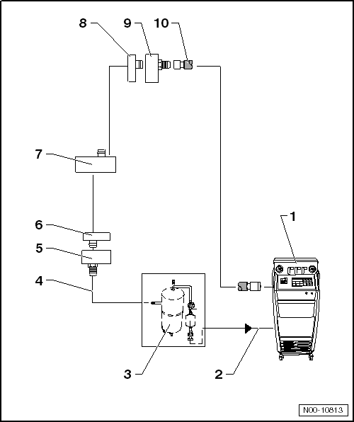
| 1 - |
Air conditioner service station |
Note
| The air conditioner compressor is purged manually. |
| – |
Extract refrigerant, if there is any in the system. |
| – |
Empty the used-oil container of the air conditioner service station. |
Note
| Some air conditioner service stations first separate the oil in the
vacuum phase and then fill it into the used-oil container. |
| – |
At the air conditioner service station, set the amount of
refrigerant to 2 kg and the amount of oil to 0. |
| – |
Connect purging device for refrigerant circuits -VAS 6336/1- or
purging device for refrigerant circuits -VAS 6337/1- between air
conditioner service station and return line for refrigerant circuit. |
| – |
Evacuate the refrigerant circuit for 10 minutes. Then observe the
vacuum gauge. If the vacuum persists, fill 2 kg of R134a refrigerant
into the circuit. Then, extract and evacuate again and repeat the
process. |
| 2 - |
Refrigerant hose of air conditioner service station |
| From the low-pressure side of the air conditioner service station
(normally coloured blue) to the outlet of the purging device for
refrigerant circuits |
| 3 - |
Purging device for refrigerant circuits |
| Different versions and different design e.g. purging device for
refrigerant circuits -VAS 6336/1- or purging device for refrigerant
circuits -VAS 6337/1-. |
| With filter, sight glass, safety valve, heating, refrigerant tank,
etc. (depending on version). |
| Depending on the design of the air conditioner service station and
the purging device for refrigerant circuits, there may be a non-return
valve installed at the outlet of the purging device for refrigerant
circuits (to assure the correct direction of refrigerant flow during
purging). |
| 4 - |
Charging hose of flushing device for refrigerant circuits |
| From connection to high-pressure side of air conditioner compressor
on refrigerant circuit (smaller diameter) to inlet of purging device for
refrigerant circuits -VAS 6336/1- or purging device for refrigerant
circuits -VAS 6337/1-. |
| 5 - |
Adapter to connection for high-pressure side on refrigerant circuit |
| Adapter -VAS 6338/3- from adapter set for refrigerant circuits -VAS
6338/1- |
Note
| If the adapter -VAS 6338/40- is available, the charging hose can be
connected directly to the air conditioner compressor. |
| 6 - |
High-pressure side refrigerant line from air conditioner compressor |
Note
| Will not be used if the adapter -VAS 6338/40- is available. |
| – |
Pull the centring pin out of the refrigerant line so that the
adapter -VAS 6338/3- fits properly. |
| 7 - |
Electrical air conditioner compressor |
| Purge the air conditioner compressor in normal direction of flow
(from low-pressure inlet to high-pressure outlet). |
| In order to purge as much refrigerant oil from the air conditioner
compressor as possible make sure that the high-pressure outlet of the
air conditioner compressor is in the lowest position possible. |
| 8 - |
Low-pressure side refrigerant line to air conditioner compressor |
Note
| Will not be used if the adapter -VAS 6338/41- is available. |
| – |
Pull the centring pin out of the refrigerant line so that the
adapter -VAS 6338/6- fits properly. |
| 9 - |
Adapter to connection for low-pressure side on refrigerant circuit |
| Adapter -VAS 6338/6- from adapter set for refrigerant circuits -VAS
6338/1- |
Note
| If the adapter -VAS 6338/41- is available, the charging hose can be
connected directly to the air conditioner compressor. |
| 10 - |
Refrigerant hose of air conditioner service station |
| From high-pressure side of the air conditioner service station
(usually coloured in red) for connection to low-pressure line or
directly to air conditioner compressor using adapter -VAS 6338/41-. |
Note
The arrows in the following illustrations show the direction
of flow of the refrigerant during purging. The refrigerant flows
against the di ...
The following table contains the various adapters that are
necessary to connect the air conditioner service station to the
refrigerant circuit for purposes of purging ...
© 2016-2026 Copyright www.vwgolf.org

 Principle circuit diagrams for various purging circuits
 Adapters for setting up purging circuits