Volkswagen Golf Service & Repair Manual: Measurement location
 Note
Note
| The vehicle shown in the illustration may differ from the actual
vehicle. |
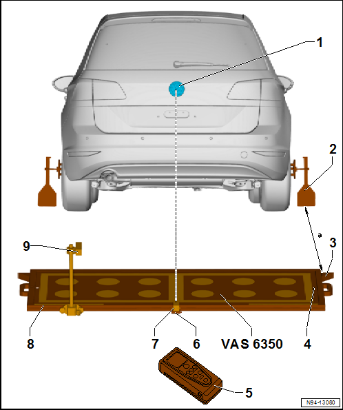
| Laser pointer aligned to centre of Volkswagen logo |
| 2 - |
Wheel centre mounting -VAS 6350/1- |
| With wheel bolt adapter (AF 17) and measuring paddle |
| to support spacing laser -VAS 6350/2- for distance measurement |
| Distance from wheel centre mountings -VAS 6350/1- on rear wheels:
Dimension -a - = 1700 ± 2 mm. |
| on calibration unit -VAS 6350- |
| to check horizontal position of calibration unit -VAS 6350- |
| 5 - |
Spacing laser -VAS 6350/2- |
| Handling
→ Operating instructions |
| Adjustable to change horizontal position of calibration unit -VAS
6350- |
| 7 - |
Linear laser -VAS 6350/3- |
| on calibration unit -VAS 6350- |
| Switching on and off
→ Operating instructions |
| to position calibration unit for lane change assist -VAS 6350/4- |
| Dimension to be set, measuring point on steel rule = 621 mm |
| 9 - |
Calibration unit for lane change assist -VAS 6350/4- |
| is changed over from the left to the right-hand side of the
measuring field during calibration |
| If assembled correctly, the mains power lead should be fitted to the
bottom left of the calibration unit (as seen facing direction of normal
travel) |
| Height of upper edge of calibration unit to hall floor: approx. 606
mm |
Removing
–
Disconnect electrical connector -2-.
–
Unscrew nut -1 ...
Extensive preliminary work is required before the actual
calibration can be carried out using → Vehicle
diagnostic tester.
Prerequis ...
Other materials:
Purging (cleaning) refrigerant circuit with refrigerant R134a
Vehicles with high-voltage system (hybrid vehicles)
Observe the additional warning instructions for working on
vehicles with high-voltage system
→ Electrical system; Rep. gr.93.
...
Repairing threaded connections
Special tools and workshop equipment
required
VAG 1331
Note
The use of penetrating fluid, contact spray or grease etc.
is prohibited since the missing ad ...
2-pack fine filler
Designation:
2-pack fine filler -LSP 784 002 A2-
Issued 06/2011
Product description
The 2-pack fine filler is a very fine, thixotropic polyester
filler.
...
© 2016-2026 Copyright www.vwgolf.org

 Removing and installing Blind Spot Monitor control unit J1086/J1087
 Preparatory measures for calibration