Volkswagen Golf Service & Repair Manual: Overview of fitting locations
| Overview of fitting locations - ABS/ESP |
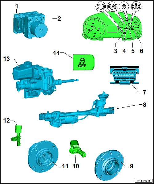
| 1 - |
ABS control unit -J104- |
| Installation location: on hydraulic unit, on passenger side of
engine compartment. |
| Do not separate connector before successfully completing
self-diagnosis. Switch ignition off before separating connector. |
| The following components are integrated into the control unit: |
| Control unit for electromechanical parking brake -J540- |
| Lateral acceleration sender -G200- |
| Longitudinal acceleration sender -G251- (depending on equipment
fitted) |
| The components cannot be renewed individually. |
| Assembly overview
→ Chapter. |
| Removing and installing
→ Chapter |
| 2 - |
ABS hydraulic unit -N55- |
| Fitting location: on passenger side of engine compartment |
| The hydraulic unit consists of the components: |
| Brake pressure sender -G201- |
| Valve block (contains inlet and outlet valves). |
| ABS hydraulic pump -V64- and valve block must not be separated from
one another. |
| Assembly overview
→ Chapter. |
| Removing and installing
→ Chapter |
| 3 - |
Brake pad warning lamp -K32- |
| Location: in dash panel insert. |
| 4 - |
ABS warning lamp -K47- |
| Location: in dash panel insert. |
| 5 - |
ESP and TCS warning lamp -K155- |
| Location: in dash panel insert. |
| 6 - |
Brake system warning lamp -K118- |
| Location: in dash panel insert. |
| 7 - |
Diagnostic connection |
| Location: Driver footwell cover. |
| 8 - |
Steering angle sender -G85- |
| Fitting location: in steering rack. |
| The steering angle sender -G85- cannot be renewed separately. |
| Removing and installing steering
→ Running gear, axles, steering; Rep. gr.48. |
| 9 - |
Wheel hub with wheel bearing |
| ABS sensor ring is installed in wheel bearing |
| 10 - |
Front right/left speed sensor -G45-/-G47- |
| Removing and installing
→ Chapter. |
| 11 - |
Wheel hub with wheel bearing |
| ABS sensor ring is installed in wheel bearing |
| 12 - |
Rear right/left speed sensor -G44-/-G46- |
| Removing and installing
→ Chapter |
| Assembly overview
→ Chapter. |
| Removing and installing
→ Chapter |
| 14 - |
TCS and ESP button -E256- |
| Two versions, therefore two fitting locations: |
| Function button in menu of infotainment system |
| Removing and installing TCS and ESP button -E256- in centre console
→ Electrical system; Rep. gr.96. |
Repair instructions for repair work on ABS
The ABS brake system is divided diagonally. The
servo-assistance is effected pneumatically by the vacuum b ...
© 2016-2026 Copyright www.vwgolf.org

 General information