Volkswagen Golf Service & Repair Manual: General information
| Repair instructions for repair work on ABS |
| The ABS brake system is divided diagonally. The
servo-assistance is effected pneumatically by the vacuum brake
servo unit. |
| Vehicles with ABS are not fitted with a mechanical brake
pressure regulator. Specially developed software in the control
unit regulates the brake force distribution on the rear axle. |
 Note Note
| Faults in the ABS do not influence the brake system and
servo assistance. The conventional brake system remains
functional even without ABS. A change in braking behaviour is to
be reckoned with. After the ABS warning lamp comes on, the rear
wheels may lock prematurely during braking. |
|
|
|
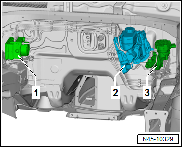
| ABS layout in LHD vehicles: |
| 1 - |
ABS hydraulic unit -N55- and ABS control unit -J104- |
| 3 - |
Brake system pressure accumulator -VX70- |
| The control unit and hydraulic are combined in a single
component. They can be separated only when removed. Hydraulic
pump must not be separated from hydraulic unit either. |
| The control unit and hydraulic are combined in a single
component. They can be separated only when removed. Hydraulic
pump must not be separated from hydraulic unit either. |
| Before carrying out repair work on the anti-lock brake
system, determine the cause of the fault as well as the control
unit code using “Guided Fault Finding”. |
| “Guided fault finding” is carried out using
→ Vehicle
diagnostic tester. |
| Disconnect battery earth strap with ignition switched off. |
| Before carrying out welding work with an electric welding
unit, note
→ General Information; Body Repairs, General Body Repairs. |
| When working with brake fluid, observe the relevant safety
precautions and notes
→ Chapter. |
| After work for which the brake system had to be opened,
bleed the brake system with brake filling and bleeding equipment
-VAS 5234-
→ Chapter. |
| During the final road test, ensure that a controlled brake
test is performed at least once (pulsations must be felt at the
brake pedal). |
| Absolute cleanliness is required when working on the
anti-lock brake system. |
| Auxiliary items containing mineral oil, e.g. oils, greases,
etc. must never be used. |
| Thoroughly clean all unions and the adjacent areas before
loosening. Do not use aggressive cleaning agents such as brake
cleanser, petrol, thinners or similar. |
| Place removed parts on a clean surface and cover. |
| If repairs cannot be carried out immediately, carefully
cover or seal open components. (Use sealing plugs from repair
kit 1 H0 698 311 A). |
| Only use lint-free cloths. |
| Only unpack replacement parts immediately prior to fitting. |
| Only use genuine packed parts. |
| When the system is open, do not work with compressed air and
do not move the vehicle. |
| The valve coils in the control unit cannot be adjusted. |
| The valve coils in the control unit cannot be renewed. |
| Pressure sensor must not be changed or damaged. |
| The pressure sensor cannot be renewed. |
| The sensor housing must not be exposed to mechanical stress. |
| No measurements must be taken on contact points of control
unit. |
| No measurements must be taken on contact points of hydraulic
unit. |
| Contact pins of hydraulic unit must not be bent or damaged. |
| The contacts cannot be renewed. |
| No contact sprays may be used on the contacts or the
pressure sensor. |
| Foreign bodies must not get between the control unit and the
hydraulic unit. |
| During painting operations, the electronic control unit can
be exposed to a maximum temperature of 95°C for only a short
period, and to a maximum of 85°C for longer periods (approx.
2 hours). Ensure that no brake fluid enters connectors. |
|
|
|
Overview of fitting locations - ABS/ESP
1 -
ABS control unit -J104-
Installation location: on hydraulic unit, on passenger side of
engine c ...
Other materials:
Spray wax (spraying wax) -D 322 100 M2
Designation:
Spray wax (spraying wax) -D 322 100 M2-
Issued 01.2011
Product description
Spray wax (spraying wax) -D 322 100 M2- is a long-term
anti-corrosion agent. The produ ...
Types of front passenger front airbag system
First read and observe the introductory information
and safety warnings
Volkswagen offers two different front
airbag systems for front passengers:
A
B
Features of the front passenger front airbag that can only be switched
...
Assembly overview - drive shaft
1 -
Outer constant velocity joint
Renew only as complete unit
Removing
→ Fig..
Installing: drive onto shaft to stop using plastic hammer
Distribute grease evenly in joint
Ch ...
© 2016-2026 Copyright www.vwgolf.org


 Overview of fitting locations