Volkswagen Golf Service & Repair Manual: Removing and installing charge air cooler
| Special tools and workshop equipment
required |
|
|
|
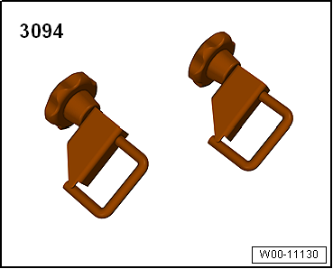
| Hose clamps up to 25 mm -3094- |
|
|
|
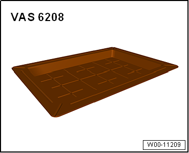
| Drip tray for workshop hoist -VAS 6208- |
|
|
|
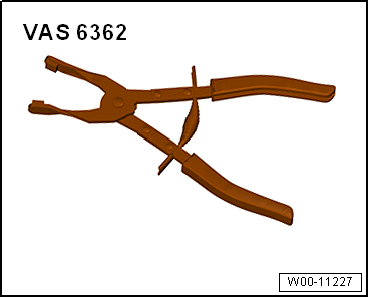
| Hose clip pliers -VAS 6362- |
| – |
Remove radiator cowl
→ Chapter. |
|
|
|
| – |
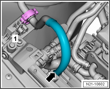
Open clip -1- and push hose
-arrow- to one side. |
| – |
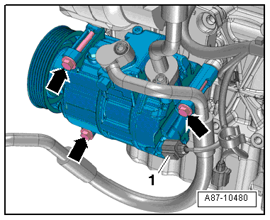
Disconnect connector -1-. |
|
|
|
| – |
Remove air conditioner compressor from bracket
-arrows- and tie it up
→ Air conditioner compressor; Removing and installing air
conditioner compressor from and to bracket; Rep. gr.87. |
| – |
Set drip tray for workshop hoist -VAS 6208- underneath. |
| – |
Clamp off coolant hoses at charge air cooler with hose
clamps -3094-. |
|
|
|
| – |
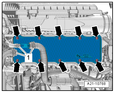
Release hose clips -1- and
detach coolant hoses. |
|
|
|
| – |
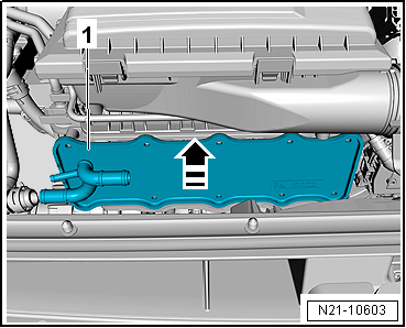
Pull charge air cooler -1-
evenly towards front (in -direction of
arrow-) out of intake manifold. |
| Installation is carried out in the reverse order; note the
following: |
|
|
|
| – |
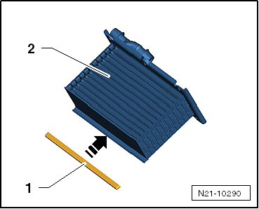
Fit sealing lip -1- in
-direction of arrow- onto charge
air cooler -2-. |
| – |
Insert new gasket into groove on intake manifold. |
|
|
|
| – |
Tighten bolts -arrows-
alternately and diagonally working from centre outwards. |
| – |
Install hose clips -1-. |
 Note Note
| If there are minor dents in the fins, refer to
→ Chapter. |
| – |
Install radiator cowl
→ Chapter. |
| – |
Check coolant level
→ Anchor. |
| → Chapter „Assembly overview - charge air system“ |
| → Heating, air conditioning system; Rep. gr.87 |
|
|
|
Charge pressure sender -GX26- consists of
Charge air pressure sender -G31-
Intake air temperature sender -G42-
...
Special tools and workshop equipment
required
Charge air system tester -V.A.G 1687-
...
Other materials:
Indicator lamp
First read and observe the introductory information
and safety warnings
Lit up
Possible cause
Solution
Engine management system fault (Electronic Power Control).
The engine should be checked by a qualified workshop
as s ...
Pressures and temperatures in the refrigerant circuit
WARNING
When working on the refrigerant circuit, observe
generally applicable safety rules and the Regulations
for Pressure Tanks.
The pressures and temperatures in the ref ...
Dimensions – lettering on rear lid, “R-Line”
Note
When fitting the lettering, observe the fitting notes
→ Anchor.
1 -
Lettering
Model designation
2 -
Height dimension
73 ± 1 mm, from upper edge of lettering to tail light.
...
© 2016-2026 Copyright www.vwgolf.org

 Removing and installing charge pressure sender -GX26-
 Checking charge air system for leaks