Volkswagen Golf Service & Repair Manual: Installing engine
| Engine/gearbox assembly secured to engine support T10497. |
 Note Note
| Renew bolts that are tightened with specified tightening
angle. |
| Renew self-locking nuts and bolts as well as gaskets, seals
and O-rings. |
| Secure all hose connections with the same types of hose
clips as original equipment
→ Electronic Parts Catalogue. |
| Reinstall all cable ties in the same locations when
installing. |
| – |
Install intermediate plate
→ Fig.. |
|
|
|
| – |
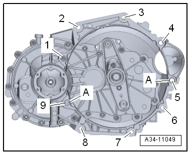
If there are no dowel sleeves -A-
in cylinder block for centring engine and gearbox, insert new
ones. |
| – |
Bolt gearbox to engine at positions
-1, 2, 3, 6, 7, 8, 9-. |
| – |
Install gearbox support. |
| – |
Take up engine/gearbox assembly with engine support T10497. |
| – |
Guide engine/gearbox assembly into body. |
|
|
|
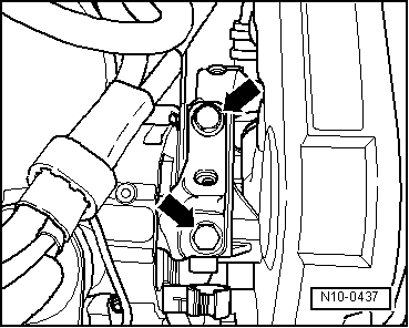
| – |
First screw bolts -arrows- for
engine mountings into stop by hand. |
|
|
|
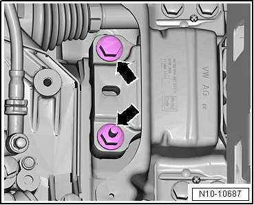
| – |
First screw bolts -arrows- for
gearbox mountings into stop by hand. |
Note
| The bolts are tightened to final torque only after adjusting
the assembly mountings
→ Chapter. |
| – |
Detach engine support T10497 from engine. |
| – |
Install starter
→ Electrical system; Rep. gr.27. |
| – |
Install air pipe
→ Chapter. |
| – |
Installing air ducts
→ Fig.. |
| Vehicles with manual gearbox |
| – |
Install clutch slave cylinder
→ Rep. gr.30. |
| – |
Install cables with cable support bracket
→ Rep. gr.34. |
| Vehicles with dual clutch gearbox |
| – |
Install selector lever cable, fit connector of mechatronic
and install all retainers on gearbox:
→ Rep. gr.34 |
| Continuation for all vehicles |
| – |
Install catalytic converter
→ Chapter. |
| Vehicles with four-wheel drive |
| – |
Install flexible coupling of propshaft to bevel box
→ Final drive, differential; Rep. gr.39. |
| – |
Install drive shafts
→ Running gear, axles, steering; Rep. gr.40. |
| – |
Install transverse link, swivel joint and coupling rod
→ Running gear, axles, steering; Rep. gr.40. |
| – |
Install air conditioner compressor
→ Heating, air conditioning; Rep. gr.87. |
| – |
Install poly V-belt
→ Chapter. |
| – |
Electrical connections and routing
→ Electrical system; Rep. gr.97 and
→ Current
flow diagrams, Electrical fault finding and Fitting locations. |
| – |
Install engine control unit -J623-
→ Chapter. |
| – |
Connect coolant hoses with plug-in connector
→ Fig.. |
| – |
Install pendulum support
→ Chapter. |
| – |
Install left and right front wheel housing liner
→ General body repairs, exterior; Rep. gr.66. |
| – |
Install front wheels
→ Running gear, axles, steering; Rep. gr.44. |
| – |
Adjust assembly mountings
→ Chapter. |
| – |
Install battery tray
→ Electrical system; Rep. gr.27. |
| – |
Install air filter housing
→ Chapter. |
Note
| Never use battery charging equipment for boost starting. |
| Danger of destroying control units through excessive
voltage. |
| – |
Replenish coolant
→ Anchor. |
Note
| Do not reuse coolant which has been drained off. |
| → Chapter „Assembly overview - assembly mountings“ |
| Securing gearbox to engine
→ Rep. gr.34 |
|
|
|
Special tools and workshop equipment
required
Engine and gearbox support -VAS 6095-
...
© 2016-2026 Copyright www.vwgolf.org

 Securing engine on engine and gearbox support