Volkswagen Golf Service & Repair Manual: Incorporation of heat exchanger for high-voltage battery into coolant circuit of
high-voltage system
 Note Note
| Fill coolant and bleed coolant circuit
→ Rep. gr.19. |
| The illustration below shows only some of the components of
the coolant circuit for the high-voltage system. For components
which are not shown here refer to
→ Rep. gr.19. |
| Incorporation of heat exchanger for high-voltage battery
into coolant circuit
→ Chapter. |
| If there is a problem with insufficient cooling output for
cooling the components of the high-voltage system and the
cooling output of the air conditioning system is OK, check the
cooling capacity of the heat exchanger for high-voltage battery
using the procedure for testing the cooling output
→ Chapter. When doing this, verify that the heat
exchanger for high-voltage battery is actually cooled down. The
operation of the refrigerant shut-off valve for high-voltage
battery heat exchanger -N542- and of the restrictor installed in
the refrigerant circuit must be OK
→ Chapter „System overview - refrigerant circuit, Golf GTE“.
If no fault in the refrigerant circuit is detected, check the
incorporation of the coolant pump for high-voltage battery
-V590-, the coolant circulation pump before power and control
electronics for electric drive -V508-, the coolant changeover
valve 1 -N632- and the coolant valve for high-voltage battery
-N688- into the coolant circuit of the high-voltage system as
well as the activation and operation of these components
→ Rep. gr.19 and vehicle diagnostic tester in “Guided
fault finding” mode (for the air conditioning system and the
hybrid battery energy management system). |
|
|
|
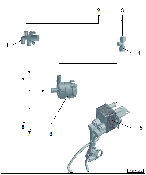
| 1 - |
Coolant valve for high-voltage battery -N688- |
| Incorporation into coolant circuit of high-voltage system
→ Rep. gr.19 |
| Removing and installing
→ Chapter |
| Check operation and activation of coolant pump for high-voltage
battery -V590- and of -N688-
→ Rep. gr.19 and vehicle diagnostic tester in “Guided fault
finding” mode (for the air conditioning system and the hybrid battery
energy management system). |
| 2 - |
Coolant return from high-voltage battery 1 -AX2- |
| Incorporation into coolant circuit of high-voltage system
→ Rep. gr.19 |
| 3 - |
Coolant supply to high-voltage battery 1 -AX2- |
| Incorporation into coolant circuit of high-voltage system
→ Rep. gr.19 |
| Bleed coolant circuit
→ Rep. gr.19. |
| 5 - |
Heat exchanger for high voltage battery |
| Incorporation into coolant circuit of high-voltage system
→ Rep. gr.19 |
| Check operation and cooling capacity of heat exchanger via the air
conditioning system
→ Chapter „Checking cooling output on vehicles with automatically
controlled air conditioning system (with high-voltage system)“
and vehicle diagnostic tester in “Guided fault finding” mode (for the
air conditioning system and the hybrid battery energy management
system). |
| Removing and installing
→ Chapter „Removing and installing heat exchanger for high-voltage
battery“ |
| 6 - |
Coolant pump for high-voltage battery -V590- |
| Incorporation into coolant circuit of high-voltage system
→ Rep. gr.19 |
| Removing and installing
→ Chapter |
| Checking operation and activation: vehicle diagnostic tester in
“Guided fault finding” mode |
Note
| The -V590- (and -N688-) are activated by the high-voltage battery 1
-AX2- (battery regulation control unit -J840-), if cooling output for
the components of the high-voltage system (the high-voltage battery 1
-AX2-, the power and control electronics for electric drive -JX1- and/or
the control unit for high-voltage battery charging unit -J1050-) is
requested vehicle diagnostic tester in “Guided fault finding” mode (for
the hybrid battery energy management system) and
→ Rep. gr.19. |
| If there is a problem with insufficient cooling output for cooling
the components of the high-voltage system, check for correct orientation
and proper operation vehicle diagnostic tester in “Guided fault finding”
mode (for the hybrid battery energy management system) and
→ Rep. gr.19. |
| For cooling the power and control electronics for electric drive
-JX1- and the control unit for high-voltage battery charging unit
-J1050-, the coolant circulation pump before power and control
electronics for electric drive -V508- and the coolant changeover valve 1
-N632- must be activated as well (by the respective engine control unit)
and they must work properly. For additional information refer to vehicle
diagnostic tester in “Guided fault finding” mode (for the hybrid battery
energy management system) and
→ Rep. gr.19. |
| 7 - |
Coolant supply from radiator for high-voltage system |
| Incorporation into coolant circuit of high-voltage system
→ Rep. gr.19 |
| 8 - |
Coolant supply to coolant circulation pump before power and control
electronics for electric drive -V508- |
| Incorporation into coolant circuit of high-voltage system
→ Rep. gr.19 |
Note
In vehicles with a high-voltage system, the high-voltage
heater (PTC) -Z115- is used as a supplementary heater.
In ve ...
Special tools and workshop equipment
required
Hose clamps, up to 25 mm -3094-
...
Other materials:
Assembly overview - rear lid
1 -
Rear lid
Removing and installing
→ Chapter
Adjusting
→ Chapter
2 -
Bonnet lock
Removing and installing
→ Chapter
3 -
Bolts
Qty. 2
20 Nm
...
Charge factor
There must be space both for liquid and vapour in a
container. As the temperature rises, the liquid expands. The
space occupied by the vapour becomes smaller. Eventually, there
will only be liquid in the container. After that time, even a
small increase ...
Water content
Only very small amounts of water are soluble in liquid
refrigerant. On the other hand, refrigerant vapour and water
vapour mix in any proportion.
Any water present in the refrigerant circuit will be carried
along as droplets. The dessica ...
© 2016-2024 Copyright www.vwgolf.org

 Incorporation of high-voltage heater (PTC) - Z115- into coolant circuit
 Removing and installing coolant valve for high-voltage battery -N688-