Volkswagen Golf Service & Repair Manual: Incorporation of high-voltage heater (PTC) - Z115- into coolant circuit
 Note Note
| In vehicles with a high-voltage system, the high-voltage
heater (PTC) -Z115- is used as a supplementary heater. |
| In vehicles with a high-voltage system and an auxiliary
heater installed as optional equipment, the high-voltage heater
(PTC) -Z115- can be used for heating the passenger compartment
instead of the auxiliary heater. For additional information,
refer to
→ Auxiliary heater, supplementary heater; Rep. gr.00. |
| In vehicles with a high-voltage system and without an
auxiliary heater installed as optional equipment, the passenger
compartment can be heated via the “Stationary air conditioning”
function and the - Z115- when the ignition is switched off and
at low ambient temperatures (or cooled via the air conditioning
system at high ambient temperatures). |
| Fill coolant and bleed coolant circuit
→ Rep. gr.19. |
| Incorporation of heat exchanger for air conditioning system
and high-voltage heater (PTC) - Z115- into coolant circuit of
engine
→ Rep. gr.19 (coolant hose schematic diagram). |
|
|
|
Note
| The -arrows- indicate the direction of
coolant flow. |
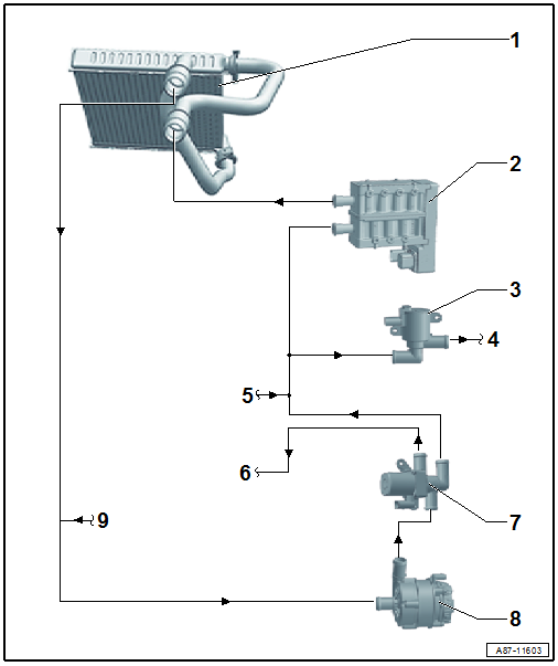
| 1 - |
Heat exchanger for heater in air conditioning unit |
| Incorporation of heat exchanger into coolant circuit of engine
→ Rep. gr.19 (coolant hose schematic diagram). |
| 2 - |
High-voltage heater (PTC) - Z115- (with high-voltage heater (PTC)
control unit - J848-) |
| Check; vehicle diagnostic tester in “Guided fault finding” mode (of
air conditioning system) and → Current flow
diagrams, Electrical fault finding and Fitting locations |
| Removing and installing
→ Chapter |
| For additional information on vehicles with an “auxiliary heater” as
optional equipment, refer to
→ Auxiliary heater; Rep. gr.00. |
| 3 - |
Coolant valve for gearbox -N488- |
| Removing and installing
→ Rep. gr.19 |
| 4 - |
Coolant supply to gearbox |
| Incorporation of auxiliary heater into coolant circuit of engine
(and gearbox)
→ Rep. gr.19 (coolant hose schematic diagram). |
| 5 - |
Coolant supply from engine |
| Incorporation of auxiliary heater into coolant circuit of engine
→ Rep. gr.19 (coolant hose schematic diagram). |
| 6 - |
Coolant return to the engine |
| Incorporation of auxiliary heater into coolant circuit of engine
→ Rep. gr.19 (coolant hose schematic diagram). |
Note
| Depending on the engine, a valve may be installed in the coolant
return section between the coolant changeover valve 2 -N633- and the
engine. The valve prevents coolant from flowing from the engine to the
-N633- when the engine is running
→ Rep. gr.19 (coolant hose schematic diagram). |
| 7 - |
Coolant changeover valve 2 -N633- |
| Incorporation of auxiliary heater into coolant circuit of engine
→ Rep. gr.19 (coolant hose schematic diagram). |
| Removing and installing
→ Rep. gr.19. |
Note
| The -N633- is activated by the respective engine control unit (e.g.
by engine control unit -J623-), if heat output is required from the air
conditioning system and if the vehicles is in electric drive mode
→ Current flow
diagrams, Electrical fault finding and Fitting locations and
vehicle diagnostic tester in “Guided fault finding” mode. |
| If there are customer complaints about poor heat output of the air
conditioning system when engine is running and/or at standstill
(irrespective of whether -Z115- is activated or not), make sure the
coolant changeover valve 2 is installed with correct orientation and
that it works properly → Current flow
diagrams, Electrical fault finding and Fitting locations and
vehicle diagnostic tester in “Guided fault finding” mode. |
| To ensure that the coolant heated by the -Z115- is conveyed through
the heat exchanger of heater and air conditioning unit, the coolant pump
for high-temperature circuit -V467- and the coolant valve for gearbox
-N488- must be activated as well (by the respective engine control
unit). To ensure that the coolant flows into the correct direction, the
non-return valves installed in the coolant circuit must be installed
correctly and they must work properly. For additional information refer
to
→ Rep. gr.19 (coolant hose schematic diagram); vehicle
diagnostic tester in “Guided fault finding” mode and
→ Current flow
diagrams, Electrical fault finding and Fitting locations. |
| 8 - |
Coolant pump for high-temperature circuit -V467- |
| Incorporation into coolant circuit of engine
→ Rep. gr.19 (coolant hose schematic diagram) |
| Removing and installing
→ Rep. gr.19 |
Note
| The -V467- is activated by the respective engine control unit (e.g.
by engine control unit -J623-), if heat output from the air conditioning
system is required → Current flow
diagrams, Electrical fault finding and Fitting locations and
vehicle diagnostic tester in “Guided fault finding” mode. |
| If there are customer complaints about poor heat output of the air
conditioning system when engine is running and/or at standstill
(irrespective of whether -Z115- is activated or not), make sure the
-V467- is installed with correct orientation and that it works properly
→ Current flow
diagrams, Electrical fault finding and Fitting locations and
vehicle diagnostic tester in “Guided fault finding” mode. |
| To ensure that the coolant heated by the -Z115- is conveyed through
the heat exchanger of heater and air conditioning unit, the coolant
changeover valve 2 -N633- and the coolant valve for gearbox -N488- must
be activated as well (by the respective engine control unit). To ensure
that the coolant flows into the correct direction, the non-return valves
installed in the coolant circuit must be installed correctly and they
must work properly. For additional information refer to
→ Rep. gr.19 (coolant hose schematic diagram); vehicle
diagnostic tester in “Guided fault finding” mode and
→ Current flow
diagrams, Electrical fault finding and Fitting locations. |
| 9 - |
Coolant return from gearbox |
| Incorporation of auxiliary heater into coolant circuit of engine
(and gearbox)
→ Rep. gr.19 (coolant hose schematic diagram). |
Note
Fill coolant and bleed coolant circuit
→ Rep. gr.19.
The illustration below shows only some of the compone ...
Other materials:
Removing and installing rear senders
Removing
–
Remove rear wheel housing liner
→ General body repairs, exterior; Rep. gr.66.
–
Press both locking lugs in direction of arrow
...
Assembly overview - door
Note
Only the left side is shown. The right side is similar
After renewal of A-pillar, the specified torque for bolts
-2 and 5- as well as for
-14 and 17- changes
1 -
Front door
Removing and installing
→ Chapter
Adjusting
...
Installing gearbox
Install in reverse order of removal, observing the
following:
Note
Renew bolts which are tightened by turning through a
specified angle.
Renew self-locking nuts and bolts, and seals, O-rings an ...
© 2016-2025 Copyright www.vwgolf.org

 Coolant circuit
 Incorporation of heat exchanger for high-voltage battery into coolant circuit of
high-voltage system
Incorporation of heat exchanger for high-voltage battery into coolant circuit of
high-voltage system