Volkswagen Golf Service & Repair Manual: Fixing position of subframe
 Note Note
| Certain repairs on vehicles require the removal of the
subframe or the entire front axle. |
| The original position of the subframe relative to the body
can be retained with the aid of qty. 4 locating pins -T10486/1-. |
| Qty. 2 locating pins -T10486/1- are a part of locating
device -T10486-. When locating device -T10486- is already being
employed, then only the addition of qty. 2 locating pins
-T10486/1- are required. |
| If the locating device -T10486- is not being employed, then
use locating device -T10486 A-. This contains qty. 4 locating
pins -T10486/1- and qty. 2 locating pins -T10486/2-. The
locating pins -T10486/2- are not required for the following
process. |
|
|
|
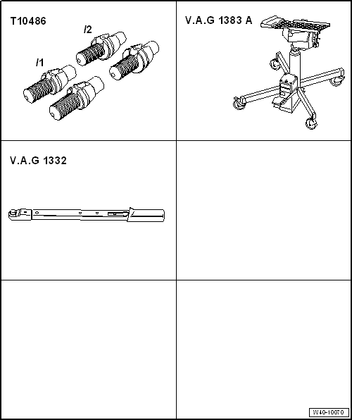
| Special tools and workshop equipment required |
| Qty. 4 locating pins -T10486/1- |
| Engine and gearbox jack -V.A.G 1383 A- with gearbox support -V.A.G
1359/2-. |
| Torque wrench -V.A.G 1332- |
| – |
De-energise high-voltage system
→ Rep. gr.93. |
| Continuation for all vehicles |
| – |
If fitted, remove front and rear noise insulation
→ General body repairs, exterior; Rep. gr.66. |
|
|
|
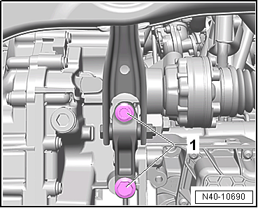
| – |
Unscrew bolts -1- for pendulum
support from gearbox. |
|
|
|
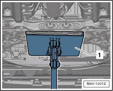
| – |
Position engine and gearbox jack -V.A.G 1383 A--1-
under subframe |
| – |
If necessary, clean thread of locating pins -T10486/1-. |
|
|
|
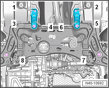
| To fix position of subframe, locating pins -T10486/1- must
be screwed one after the other into positions
-3-, -5-,
-7- and -8-. |
Note
| The locating pins -T10486/1- must NOT be tightened to more
than 20 Nm, otherwise the threads of the locating pin will be
damaged. |
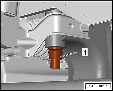
| Fixing position of subframe at rear |
|
|
|
| – |
Unscrew bolt -3-, and remove
support -4-. |
|
|
|
| – |
Insert locating pins -T10486/1--1-
and tighten to 20 Nm. |
|
|
|
| – |
Unscrew bolt -5-, and remove
support -6-. |
| – |
Insert locating pins -T10486/1- and tighten to 20 Nm. |
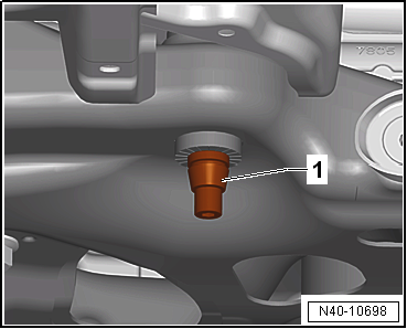
| Fixing position of subframe at front |
|
|
|
| – |
Insert locating pins -T10486/1--1-
and tighten to 20 Nm. |
|
|
|
| – |
Insert locating pins -T10486/1- and tighten to 20 Nm. |
| The fixing of the subframe is completed when all the above
mentioned bolts have been replaced consecutively with the
locating pins -T10486/1-. |
| The position of the subframe is now fixed. |
| Removing locating pins -T10486/1- |
| Remove in reverse order, observing the following: |
| – |
Always only unscrew one locating pin at a time and replace
it with a new bolt. |
| – |
On vehicles with vehicle level sender, carry out basic
settings for wheel damper electronics → Vehicle
diagnostic tester. |
| → Chapter „Assembly overview - subframe“ |
| Bolts for pendulum support, except for e-Golf
→ Rep. gr.10 |
| Bolts for pendulum support, e-Golf
→ Electrical system; Rep. gr.93 |
| Bolts for noise insulation
→ General body repairs, exterior; Rep. gr.66. |
| If a crooked steering wheel is determined during the road
test even though locating pins -T10486/1- were used, check wheel
alignment. In this case the wheel alignment test results must be
archived in the vehicle files. |
|
|
|
Special tools and workshop equipment
required
Torque wrench -V.A.G 1332-
Removin ...
© 2016-2026 Copyright www.vwgolf.org

 Removing and installing coupling rod