Volkswagen Golf Owners Manual: Changing the bulb in the number plate light
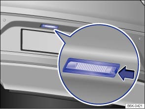
Fig. 241 In the rear bumper: number plate light
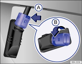
Fig. 242 Number plate light: removing the bulb holder
 First read and observe the introductory information
and safety warnings
First read and observe the introductory information
and safety warnings| The actions should only be carried out in the specified order: | ||
|---|---|---|
| 1. | Observe and follow the instructions on the checklist. | |
| 2. | Press the retaining lug for the number plate in the direction of the arrow . | |
| 3. | Pull the number plate light out slightly. | |
| 4. | Push the catch on the connector in the direction of the arrow and pull the connector out. | |
| 5. | Turn the bulb holder in the direction of the arrow and pull it out together with the bulb. | |
| 6. | Replace the defective bulb with a new bulb of the same type. | |
| 7. | Insert the bulb holder into the number plate light and turn it as far as it will go in the opposite direction to the arrow . | |
| 8. | Connect the connector to the bulb holder. | |
| 9. | Carefully put the number plate light into the opening in the body. Ensure that you put the number plate light in the right way round. | |
| 10. | Push the number plate light into the bumper until it clicks into place. | |

There are various types of number plate lights, so the design of the bulb holder may vary from those shown in the illustrations.
It is not possible to change the LEDs in number plate lights with LED technology. Proceed to a qualified workshop.
 Changing bulbs in the tail light cluster in the body
Fig. 239 On the side of the luggage compartment:
removing the tail light cluster
Fig. 240 Tail light cluster in the body:
removing the bulb holder ① to ⑤: release tabs
First read and obser ...

Other materials:
Removing and installing TV tuner, eGolf
Special tools and workshop equipment
required
Protective cap for wiring harness connector -VAS 6223/9-
If the control unit is replaced, select the
Replace function of the resp ...
Removing and installing model designation on radiator grille
Note
The description applies for all emblems. Here the “GTI”
emblem is shown as an example.
Removing
–
Removing radiator grille
→ Chapter
– ...
Refrigerant circuit with expansion valve and evaporator
1 -
Evaporator
2 -
Expansion valve
3 -
Valve for extracting, charging and measuring
4 -
Receiver with dessicant bag or cartridge
...
