Volkswagen Golf Service & Repair Manual: Assembly overview - flaps and partitions in air distribution housing
 Note Note
| The illustration shows a left-hand drive vehicle. |
|
|
|
Note
| -Arrow- = Direction of travel |
| → Chapter „Assembly overview - heater and air conditioning unit“. |
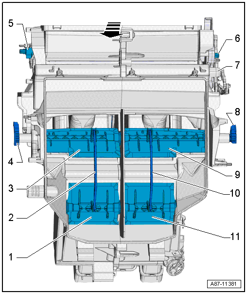
| 1 - |
Right heated air flap |
| Activated via right cold air flap |
| Heater unit and air conditioning system with electric/manual
controls |
| Activated jointly via shaft of left cold air flap by temperature
flap control motor -V68- via left actuating lever |
| Activated by temperature flap control motor -V159- via right
actuating lever |
| 4 - |
Actuating lever on right of temperature control flap |
| Activated by temperature flap control motor -V159- |
| 5 - |
Actuating lever of flap for “defrost”. |
| To windscreen and door windows |
| Activated by defroster flap control motor -V107- |
| 6 - |
Actuating lever of flap for “defrost”. |
| To windscreen and door windows |
| Only heater unit and air conditioning system with electric/manual
controls. |
| Activated by air distribution flap control motor -V428- via
defroster and air distribution actuation unit |
| 7 - |
Air distribution flap actuating lever |
| Heater unit and air conditioning system with electric/manual
controls |
| Activated by air distribution flap control motor -V428- via
defroster and air distribution actuation unit |
| Activated by front air distribution flap control motor -V426- via
defroster and air distribution actuation unit |
| Heater unit and air conditioning system with electric/manual
controls |
| Activated by temperature flap control motor -V68- |
| Activated by temperature flap control motor -V158- |
| Heater unit and air conditioning system with electric/manual
controls |
| Activated by temperature flap control motor -V68- via left actuating
lever |
| Activated by temperature flap control motor -V158- via left
actuating lever |
| 11 - |
Left heated air flap |
| Activated via left cold air flap |
Note
| The illustration shows a left-hand drive vehicle. |
|
|
|
Note
| -Arrow- = Direction of travel |
| → Chapter „Assembly overview - heater and air conditioning unit“. |
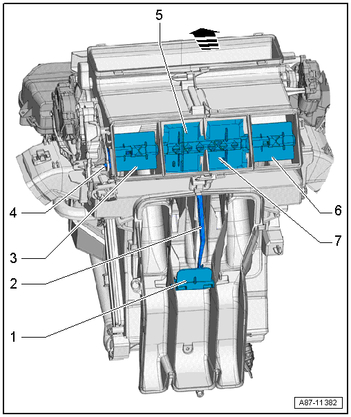
| 1 - |
Flap for rear air duct |
| Heater unit and air conditioning system with electric/manual
controls |
| The air duct is sealed with a plug |
| Not always fitted with heater unit and air conditioning system with
electric/manual controls depending on make (not needed as air duct is
sealed off). |
| Climatronic (depending on vehicle) |
| For rear vent in centre console. |
| Equipment version with Climatronic. |
| Not always fitted with heater unit and air conditioning system with
electric/manual controls -1-. |
| 3 - |
Left flap for left dash panel vent |
| For actuation of vent flaps |
| Activated via actuation unit
→ Item. |
| 5 - |
Left flap for centre dash panel vent |
| 6 - |
Right flap for right dash panel vent |
| 7 - |
Right flap for centre dash panel vent |
Note
There are different designs and makes of heater and air
conditioning unit. The individual components of the various
heaters and air conditio ...
Special tools and workshop equipment
required
Torque wrench -V.A.G 1331/- (5…50 Nm)
& ...
© 2016-2026 Copyright www.vwgolf.org

 Assembly overview - evaporator housing
 Removing and installing heater and air conditioning unit