Volkswagen Golf Service & Repair Manual: Assembly overview - control unit and hydraulic unit, RHD vehicles
| 1 - |
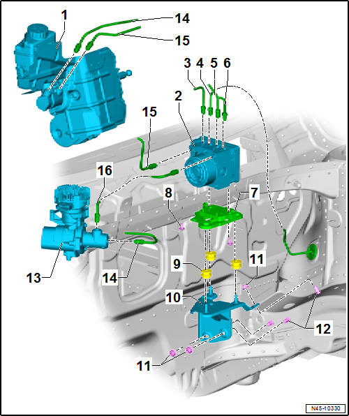
Brake servo and brake master cylinder |
| Assembly overview
→ Chapter. |
| Checking brake servo → Vehicle
diagnostic tester |
| Removing and installing
→ Chapter |
| Removing and installing brake master cylinder
→ Chapter. |
| 2 - |
ABS hydraulic unit -N55- with ABS control unit -J104- |
| Fitting location overview
→ Chapter |
| Assembly overview
→ Chapter. |
| Removing and installing
→ Chapter |
| Separating ABS control unit -J104- from ABS hydraulic unit -N55-
→ Chapter |
| Attaching ABS control unit -J104- to ABS hydraulic unit -N55-
→ Chapter |
| Connecting brake line
→ Chapter |
| To rear right brake caliper |
| Identification: Ш 5.25 mm and flare nut with thread M 10 x 1 |
| Repairing brake lines
→ Chapter |
| To front left brake caliper. |
| Identification: Ш 5.25 mm and flare nut with thread M 10 x 1 |
| Repairing brake lines
→ Chapter |
| To front right brake caliper |
| Identification: Ш 5.25 mm and flare nut with thread M 10 x 1 |
| Repairing brake lines
→ Chapter |
| To rear left brake caliper |
| Identification: Ш 5.25 mm and flare nut with thread M 10 x 1 |
| Repairing brake lines
→ Chapter |
| Check for secure seating after installing |
| Ensure that rubber dampers of retainer are not pressed out of
bracket when installing. After installation, check that the ABS
hydraulic unit -N55- is firmly seated, or malfunction can occur. |
| 13 - |
Brake system pressure accumulator -VX70- |
| Assembly overview
→ Chapter. |
| Removing and installing
→ Chapter |
| Secondary piston circuit of brake master cylinder to brake system
pressure accumulator -VX70- |
| Identification: Ш 6 mm and flare nut with thread M 12 x 1 |
| Repairing brake lines
→ Chapter |
| From primary piston circuit of brake master cylinder to hydraulic
unit. |
| Identification: Ш 6 mm and flare nut with thread M 12 x 1 |
| Repairing brake lines
→ Chapter |
| From brake system pressure accumulator -VX70- to ABS hydraulic unit
-N55- |
| Identification: Ш 6 mm and flare nut with thread M 12 x 1 |
| Repairing brake lines
→ Chapter |
1 -
Brake line
From primary piston circuit of brake master cylinder to hydraulic
unit.
Identification: Ш 6 mm and flare nut with ...
Special tools and workshop equipment required
Torque wrench -V.A.G 1331-
Torque wrench -V.A.G 1410-
Brake pedal depressor -V.A.G 1869/2- ...
Other materials:
Installing brackets for parking aid system
Special tools and workshop equipment
required
Installation tool for PDC bracket -VAS 6614-
Materials
Cartridge gun ...
Remote control
Fig. 185 Auxiliary heater: remote control
Fig. 186 Auxiliary heater: battery cover
for the remote control
First read and observe the introductory information
and safety warnings
Meaning
Switches on the auxiliary heater.
...
Removing and installing track rod
Special tools and workshop equipment
required
Torque wrench -V.A.G 1331-
Torque wrench -V.A.G 1332-
...
© 2016-2026 Copyright www.vwgolf.org

 Assembly overview - control unit and hydraulic unit, LHD vehicles
 Removing and installing control unit and hydraulic unit, LHD