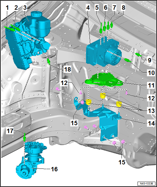
Volkswagen Golf Service & Repair Manual: Assembly overview - control unit and hydraulic unit, LHD vehicles
| From primary piston circuit of brake master cylinder to hydraulic
unit. |
| Identification: Ш 6 mm and flare nut with thread M 12 x 1 |
| From secondary piston circuit of brake master cylinder to hydraulic
unit. |
| Identification: Ш 6 mm and flare nut with thread M 12 x 1 |
| Assembly overview
→ Chapter. |
| Checking brake servo → Vehicle
diagnostic tester |
| Removing and installing
→ Chapter |
| 4 - |
ABS control unit -J104- and ABS hydraulic unit -N55- |
| Removing and installing
→ Chapter |
| To rear right brake caliper |
| Identification: Ш 5.25 mm and flare nut with thread M 10 x 1 |
| To front left brake caliper. |
| Identification: Ш 5.25 mm and flare nut with thread M 10 x 1 |
| To front right brake caliper |
| Identification: Ш 5.25 mm and flare nut with thread M 10 x 1 |
| To rear left brake caliper |
| Identification: Ш 5.25 mm and flare nut with thread M 10 x 1 |
| To primary piston circuit of brake master cylinder |
| Identification: Ш 6 mm and flare nut with thread M 12 x 1 |
| To secondary piston circuit of brake master cylinder |
| Identification: Ш 6 mm and flare nut with thread M 12 x 1 |
| Ensure that rubber dampers of retainer are not pressed out of
bracket when installing. After installation, check that the ABS
hydraulic unit -N55- is firmly seated, or malfunction can occur. |
| 16 - |
Brake system pressure accumulator -VX70- |
| Assembly overview
→ Chapter. |
| Removing and installing
→ Chapter |
| Identification: Ш 5.25 mm and flare nut with thread M 10 x 1 |
| To brake system pressure accumulator -VX70- |
| Identification: Ш 5.25 mm and flare nut with thread M 10 x 1 |
1 -
Brake servo and brake master cylinder
Assembly overview
→ Chapter.
Checking brake servo → Vehicle
diagnos ...
© 2016-2026 Copyright www.vwgolf.org


 Assembly overview - control unit and hydraulic unit, RHD vehicles